13
1
• USB2 Power Selector: JP5
Function Jumper Setting
VCC5V Short pins1-2
SB5V Short pins2-3
Install the Mainboard
Install the mainboard in a system chassis (case). The board is a
Micro ATX size mainboard. You can install this mainboard in an
ATX case. Make sure your case has an I/O cover plate matching
the ports on this mainboard.
Install the mainboard in a case. Follow the case manufacturer’s
instructions to use the hardware and internal mounting points on
the chassis.
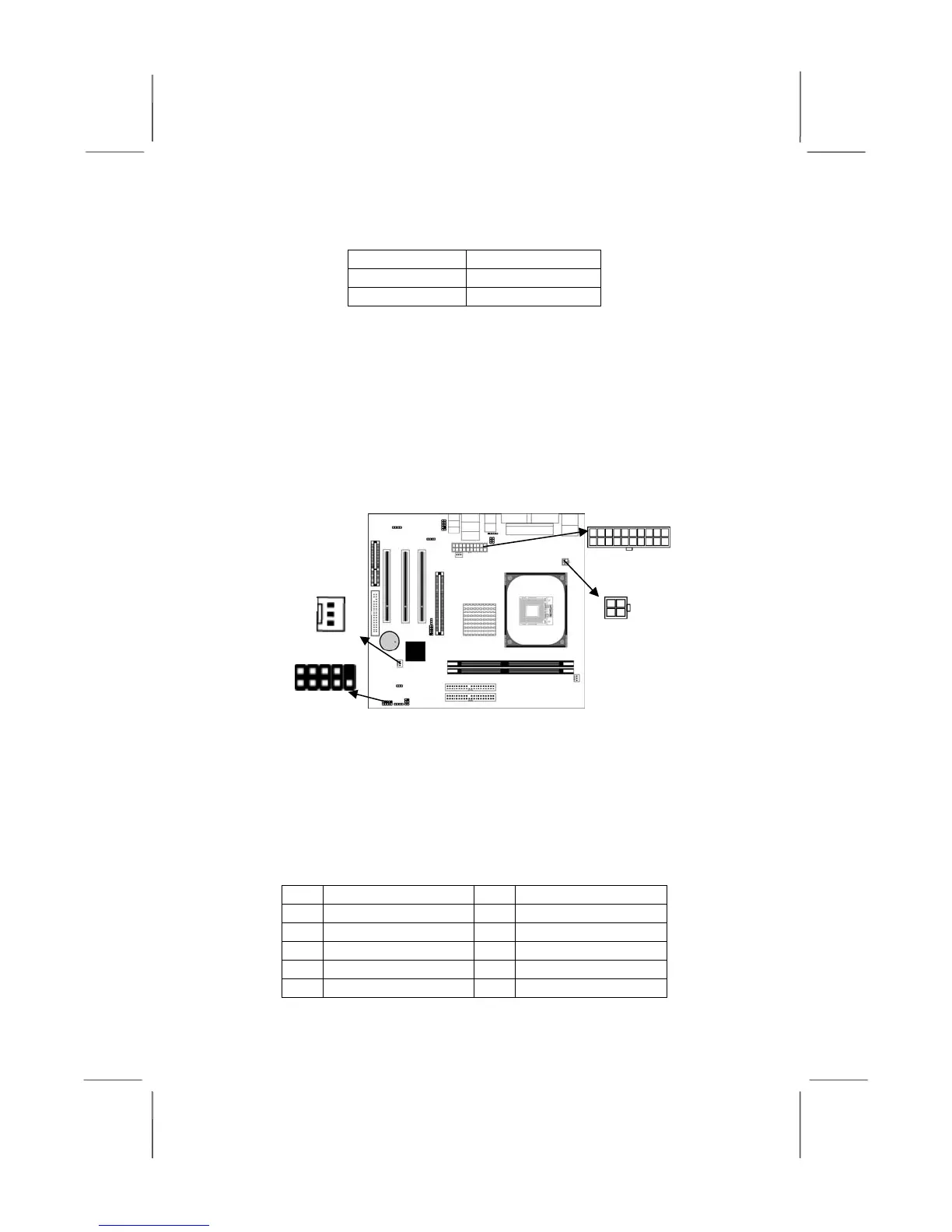
Connect the power connector from the power supply to the
ATXPW1 connector on the mainboard. CPUPW1 is the CPU
Vcore power connector.
If there is a cooling fan installed in the system chassis, connect the
cable from the cooling fan to the SYSFAN1 fan power connector
on the mainboard.
Connect the case switches and indicator LEDs to the PANEL1
connector. Here is a list of the PANEL1 pin assignments.
Pin Signal Pin Signal
1 HD_LED_P 2 FP PWR/SLP
3 HD_LED_N 4 FP PWR/SLP
5 RESET_SW_N 6 POWER_SW_P
7 RESET_SW_P 8 POWER_SW_N
9 RSVD_DNU 10 KEY
SYSFAN2
1
ATXPW1
CPUPW1
1
PANEL1
 Loading...