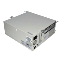
12
Checking connections
Checking connections
The most common causes of hardware problems are faulty or loose connections. Before
you replace any parts of the Fiery X3eTY, verify all cables and connections. If you have
conclude that all external connections are working properly, check the internal
connections.
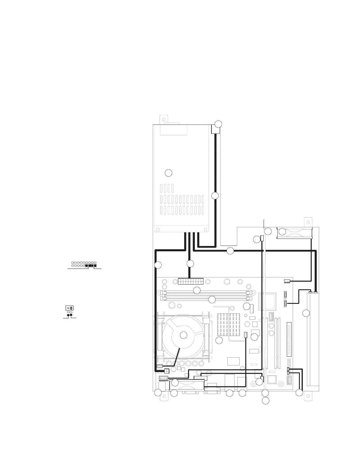
FIGURE H Cable diagram
Key to components, cabling, and
motherboard labels
1. Fiery X3eTY motherboard
2. HDD, cable to SATA1
3. DIMM slots:
a) DIMM2 for standard DIMM
b) DIMM1 for optional DIMM
4. Battery in battery socket F4
5. CPU cooling assembly to FAN1
6. Interface cable connectors to
print engine:
a) interface board connector
b) COPIER port in LAN2
7. LAN port in LAN1
8. USB Type A ports (3) in USB
9. USB Type B port in USBTYPE-B
10. Interface board in PC11:
a) J632 to motherboard JP22
b) J20 to motherboard J29
11. Service switches on interface board
12. Soft power button cables to Front
Panel connector:
13. Bottom fan to FAN3
14. Top fan to FAN2
15. AC power switch:
16. Power supply:
a) to AC power switch
b) to HDD
c) to J18
d) to J11
17. BIOS chip
NOTE: Connectors that are not
described are not used.
SW SW LED
Front Panel
White
Black
1
2
3a
4
5
7
8
9
10
6a
6b
11
12
HDD
Motherboard
Interface Board
Power supply
AC power switch
Bottom fan
Top fan
14
13
15
16
3b
16a
16b
16c
16d
10a
10b
17
 Loading...