15
Removing and replacing the motherboard
Removing and replacing the motherboard
When the Fiery X3eTY motherboard must be removed and replaced, use the following
procedures. You can use a magnetic screwdriver if it is rated for electronic components.
TO REMOVE THE FIERY X3ETY MOTHERBOARD
CAUTION: Make sure you use an ESD grounding wrist strap and follow standard
ESD precautions while performing this procedure.
1. If possible, print a Configuration page so that you have a record of system settings and
features (see page 35).
2. Remove the Fiery X3eTY from the print engine, as described on page 10.
3. Remove the interface board according to the procedure on page 18.
4. Disconnect the following cables from the motherboard (see Figure H on page 12):
N
OTE: Learn the cable routing before you cut any tie-wraps so that you can properly
arrange the cabling later with new tie-wraps. Tie-wraps are included in the motherboard
spare kit.
•Power supply cable at J11
•Power supply cable at J18
• HDD cable at SATA1
•Enclosed fan cables at FAN2 and FAN3
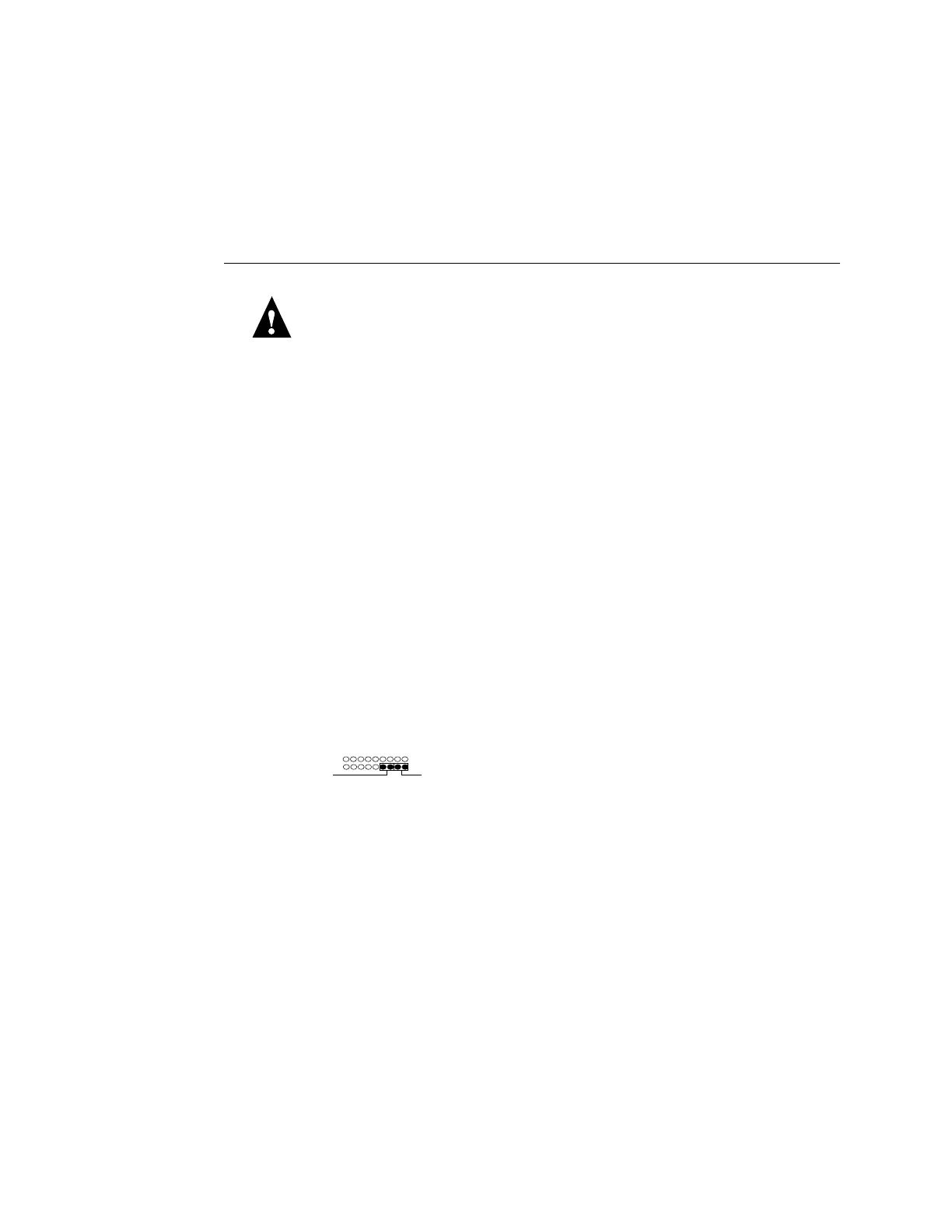
•Soft power button cables at connector labeled “Front Panel”
The cables are labeled SW and SW LED:
5. Remove the screws (five, maximum) that secure the Fiery X3eTY motherboard to the pan.
6. Slide the motherboard away from the connector panel cutouts.
Make sure to note the position of the “metal fingers” on the USB connectors so that you
can re-position them later.
7. Lift the motherboard out of the pan and set it on a flat anti-static surface.
As you remove it, be careful to avoid stressing the motherboard or the surrounding cables
in the pan.
8. If you are replacing the motherboard with a new motherboard, then remove the CPU
and CPU cooling assembly, the DIMMs, and the BIOS chip from the old motherboard
(see “Removing and replacing components” on page 17).
SW SW LED
Front Pane
 Loading...