04/2011 - Art. Nr. 4200 1037 0000A 23
Function
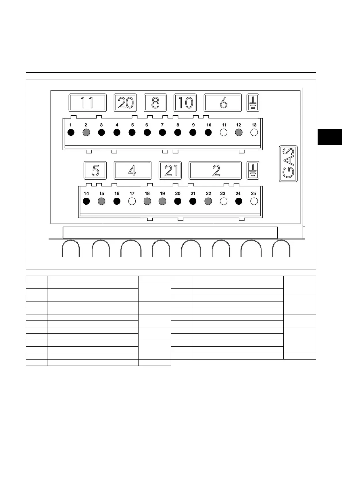
Allocation chart
Connection socket
Terminal Designation Connector no. Terminal Designation Connector no.
1 Flame monitor signal
11
14 Ignition transformer phase
5
2 Neutral 15 Neutral
3 Live 16 Burner motor phase
4
4 Remote release signal
20
17 Earth
5 Live 18 Neutral
6Live
8
19 Neutral
21
7 Gas pressostat signal 20 Fault display phase
8 Air pressure switch signal
10
21 Safety valve phase
1
9 Live 22 Neutral
10 Live
6
23 Earth
11 Earth 24 Main gas valve phase
12 Neutral 25 Earth
13 Earth
Connector
no.
Terminal
Terminal
Connector
no.
Flame monitor
Remote
unlocking
Firing
Burner motor
Air pressure
switch
Gas pressostat L1 power supply
Malfunction light
Solenoid valve
Earth
Earth
 Loading...