INSTALLATION INSTRUCTIONS | SMART LINE BOILING PAN
20 DOC N° ST0 9183-02 EN | 10-2018
INSTALLATION
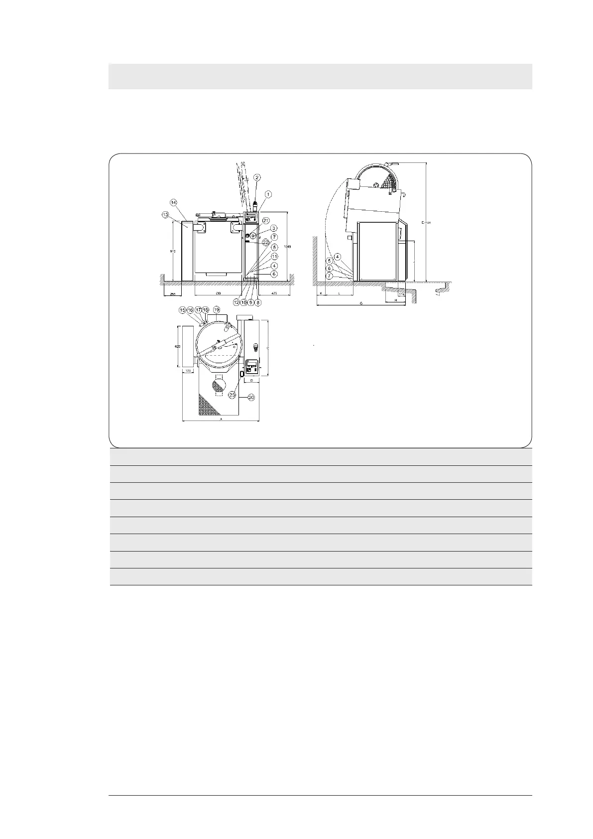
12. INSTALLATION DIAGRAM
12.1 Dimensions and connection points (SM6B, SM6V, S6MP)
Volume Dimensions (mm) .
(L) A Ø B C D E G H J K L
50 990 538 838 230 1644 1245 250 638 200 250
80 1160 705 838 230 1792 1375 305 620 200 375
100 1160 705 838 230 1792 1420 305 620 200 425
150 1300 816 988 250 1909 1480 305 620 200 335
200 1345 867 988 250 1964 1550 305 620 200 405
300 1495 1018 988 250 2118 1600 305 620 200 455
1. Control panel
2. Hand shower (accessory)
3. Emergency stop
4. Electrical connection from rear
5. Water connection, hot water from rear:
DN15 (G1/2”) internal thread
6. Water connection, cold water from rear:
DN20 (G3/4”) male thread
7. Equipotential screw
8. Foundation frame or mounting frame
(accessory)
9. Water connection, cold water from floor:
DN20 (G3/4”) male thread
10. Water connection, hot water from floor:
DN15(G1/2”) Int.thread
11. Steam connection from rear 110-170 kPa
(1,1-1,7 bar): DN20 (G3/4”) Int.thread
12. Electrical connection from floor
13. Condensation connection:
DN20 (G3/4”) Internal thread
14. Left column (accessory)
15. Steam trap
16. Manometer
17. Safety valve
18 Hydrostatic testing tap
19. Water connection, filling pressure vessel:
DN15(G1/2”) Internal thread
20. Floor drain (accessory)
21. Push button, agitation without grid (SMARTMIX)
22. USB port (Option)
23. Foot pedal (Option)
Fig. 1
 Loading...