INSTALLATION INSTRUCTIONS | SMART LINE BOILING PAN
EN | 10-2018 DOC N° ST0 9183-02 31
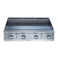
14. POSITIONING OF BOILING PANS IN THE FIELD
1. Dismantle right columns front, side plate
and rear.
2. Disconnect the transport protection from
the support leg.
3. Remove the right column from the bottom of
the packaging.
4. Disconnect the vessels transport leg.
5. Lift the pan at the appropriate lifting points
(e.g. the shaft between vessel and column
and at the vessel’s transport leg M.
NOTE
Please follow these instructions
• The centre of gravity is pushed forwards. For
supplementary weight data, see chapter “2.
Models”
6. Take care with the cables and the front of
the right column when dismantling and
transporting.
7. Lift the pan into position.
8. Screw the right column and the left column
onto the wall or mounting frames.
9. Lift the next pan into place and screw in.
10. Connect the electrical cables and check
that the tip motor is running in the right
direction.
11. Connect the cold and hot water lines.
NOTE
Please follow these instructions
• If the pan has a flow meter, the maximum flow
will be 45 l/minute.
• Incoming water lines are supplied with shut-
off valves, which are installed at the bottom of
the column as close to the floor as possible;
these are not supplied.
• Ensure that there is a tight fir between the
column and the wall or mounting frame. Seal
with soft compound, for example, on the in-
side of the column facing the frame. If neces-
sary, the outside of the column can also be
sealed to the frame.
14.1 Models: SM6B, SM6V, SM6P
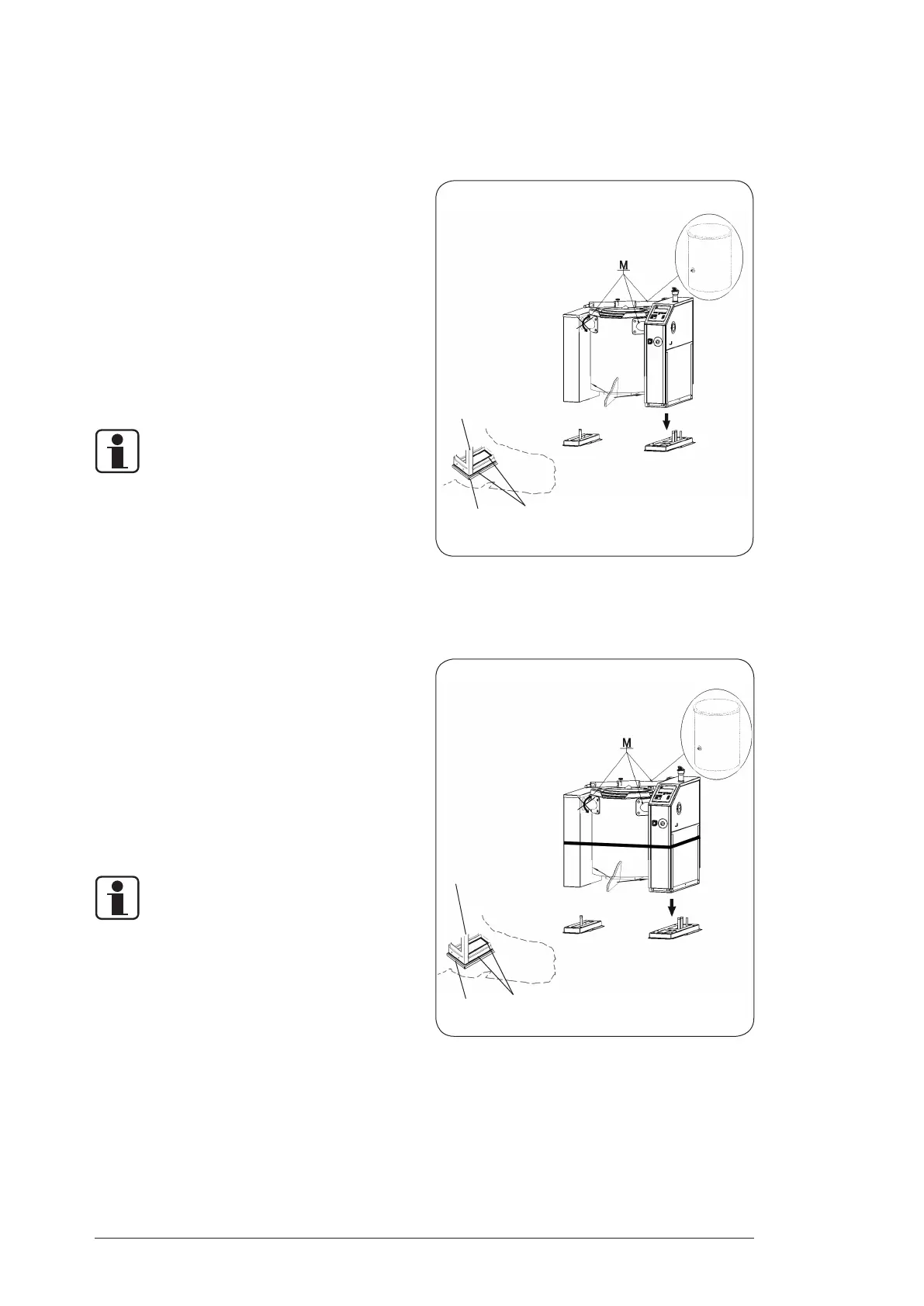
14.2 Models: Boiling pan
with the option ice water cooling
SV6I, SP6I
Column
Frame Sealing compound
Column
Frame Sealing compound
Fig. 19
Fig. 20
 Loading...