23
5 6 4 1
2391312811107
Product description
EIA485 standard.
7 RF Monitor connector – BNC connector to connect external measuring devices, it
allows the measure of low level RF signal (0dBm full scale). Warning: this monitor is
not calibrated, so a perfectly constant output level, with frequency, is not guaranteed. It
must NOT used to measure the output power, nor to measure harmonic components.
8
Ventilation grid – it promotes cooling.
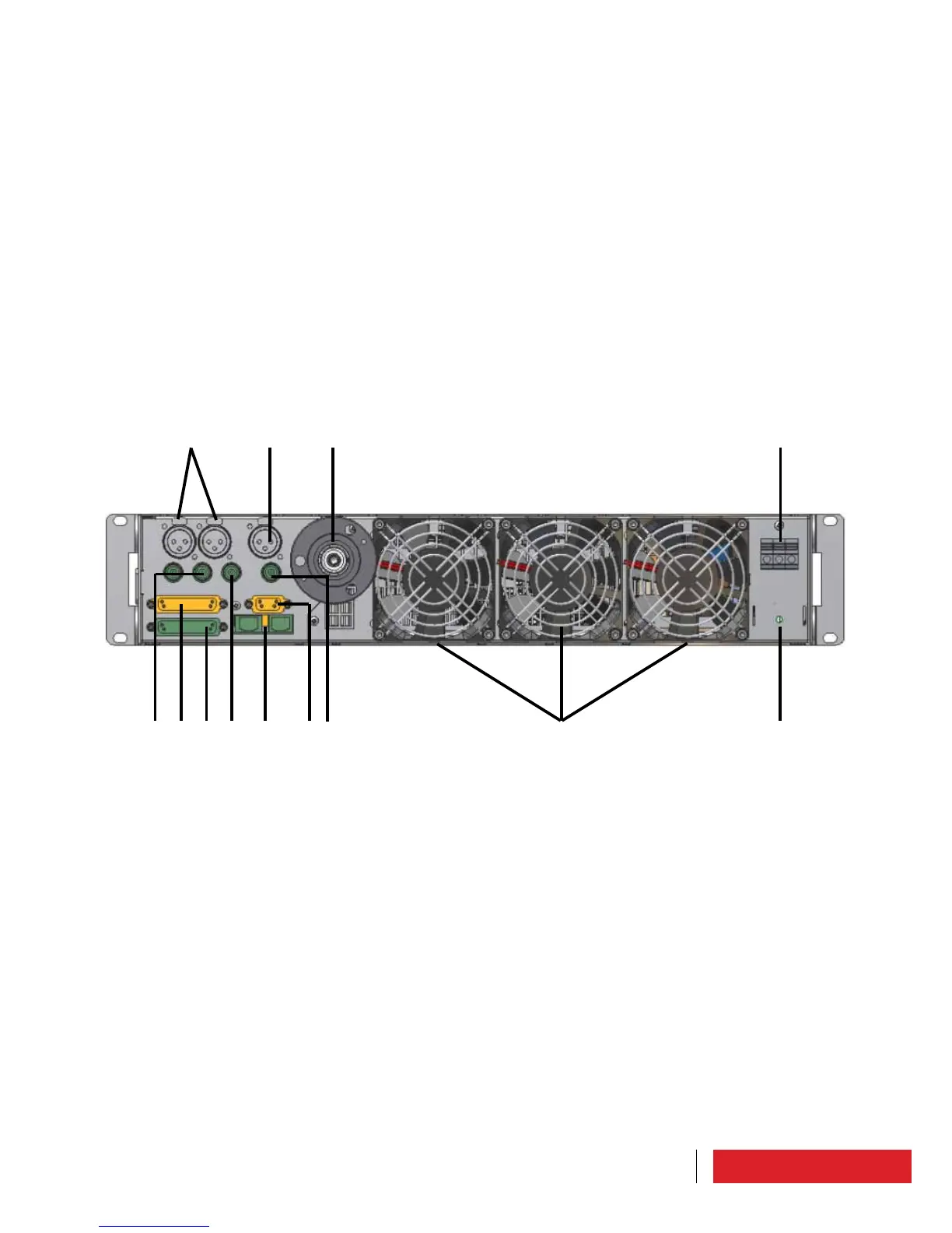
5.3 Rear Panel
1 Power terminals – to connect with the power supply. These terminals are protected by
a special box to ensure the operator electrical safety.
2 Screw for grounding – screw to put on ground the device.
3 Fans – fans for cooling. Depending on the model they may be present in num-
bers equal to 2 or 3, and have specifications equal to 24Vdc/1.65A39, 6W or
24Vdc/0.56A/13W.
4 RF connector – depending on power output it can be either 7/16 or N.
5 LEFT/RIGHT (or MONO) analog inputs – XLR connectors for audio inputs, left or right
channels. The RIGHT input can be used as MONO input. They may be present or not,
depending on the model.
6 AES/EBU digital input – XLR connector for AES/EBU digital audio input. It may be pre-
sent or not, depending on the model purchased.
 Loading...