24
5
9
4
8
3
7
2
6
1
Product description
7 AUX inputs – BNC connectors for channel modulating auxiliary input (RDS/SCA).
8 MPX input – BNC connector for the stereo modulating compound signal input.
9 Monitor/19kHz OUT connector – output connector, BNC type, to monitor MPX, RDS or
SCA signals, or to extract 19kHz signal of stereo subcarrier to synchronization. Set by
hardware (jumper JP3).
10 TC/TS connector – DB25 connector to remote TeleControl and TeleSignal (optional).
11 Profiles connector – DB25 connector to use the transmitter as reserve in N+1 system
(optional).
12 TCP/IP, RESERVED connector – connector to remote connection (optional).
13 EIA485 connector – DB9 connector to connect a telemetry, according to EIA485 stan-
dard (optional).
5.4 External connectors description
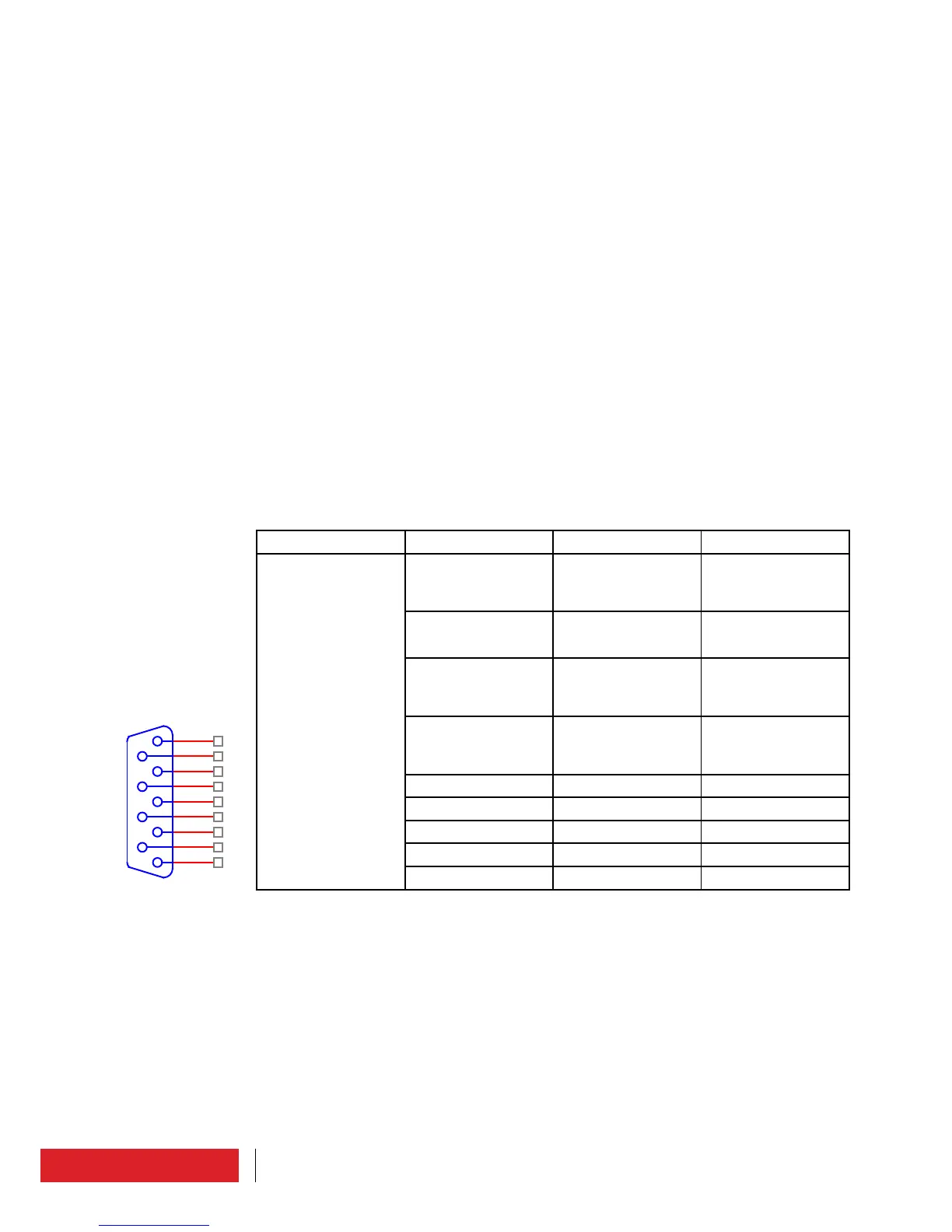
5.4.1 Interface connector
N° 6 Front panel (DB9 Female)
Connector Pin Description Note
CN3 on board
TG2U3A899
1 TX_1 Filtered output 485
Differential signal
“positive”
2 /TX_1 Filtered output 485
Differential signal
“negative”
3 RX_1 Filtered input 485
Differential signal
“positive”
4 / RX_1 Filtered input 485
Differential signal
“negative”
5 Common ground
6 Common ground
7 Common ground
8 Common ground
9 Common ground
 Loading...