25
Reference Manual
00809-0100-4853, Rev AB
Installation
January 2017
Installation
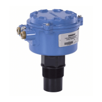
Figure 3-8. Simulate and Security Switches
3.4.6 Wire, ground, and power
Use a copper wire of sufficient size to ensure the voltage across the transmitter power terminals does not
drop below 9 Vdc. Power supply voltage can be variable, especially under abnormal conditions such as
when operating on battery backup. A minimum of 12 Vdc under normal operating conditions is
recommended. Shielded twisted pair Type A cable is recommended.
Note
The power terminals are polarity insensitive, which means the electrical polarity of the power leads does
not matter when connecting to the power terminals. If polarity sensitive devices are connected to the
segment, terminal polarity should be followed.
3.4.7 Signal wiring and shield grounding
Do not run signal wiring in conduit or open trays with power wiring, or near heavy electrical equipment.
Grounding terminations are provided on the outside of the electronics housing and inside the terminal
compartment. These grounds are used when transient protection terminal blocks are installed or to
fulfill local regulations.
1. Remove the field terminals housing cover.
2. To power the transmitter, connect the power leads to the terminals indicated on the terminal block
label.
3. Tighten the terminal screws to ensure full contact with terminal block screw and washer. When using
a direct wiring method, wrap wire clockwise to ensure it is in place when tightening the terminal
block screw. When wiring to the screw terminals, the use of crimped legs is recommended.
Note
The use of a pin or ferrule wire terminal is not recommended as the connection may be more susceptible
to loosening over time.
A. Security unlocked position
B. Security switch
C. Security locked position
D. Simulate disabled position
E. Simulate switch
F. Simulate enabled position
SECURITY
SIMULATE
ENABLE
DISABLE
C
D
E
F
B
A

 Loading...