31
Reference Manual
00809-0100-4853, Rev AB
Installation
January 2017
Installation
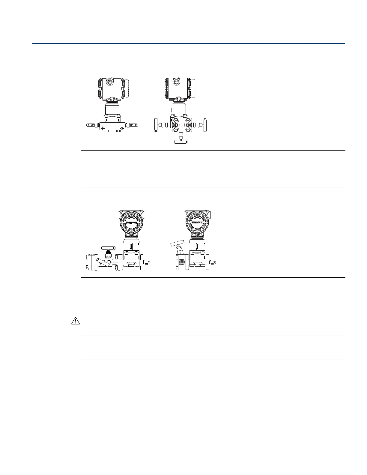
Figure 3-15. Rosemount 305 Manifold Styles
The Rosemount 304 comes in two basic styles: traditional (flange x flange and flange x pipe) and wafer.
The traditional manifold comes in 2-, 3-, and 5-valve configurations. The wafer manifold comes in three-
and five-valve configurations.
Figure 3-16. Rosemount 304 Manifold Styles
3.5.1 Rosemount 305 Integral Manifold installation procedure
To install a Rosemount 305 Integral Manifold to a Rosemount 3051SMV:
1. Inspect the PTFE SuperModule
™
O-rings. If the O-rings are undamaged, reusing them is
recommended. If the O-rings are damaged (e.g. nicks), replace them with new O-rings.
Note
If replacing the O-rings, be careful not to scratch or deface the O-ring grooves or the surface of the
isolating diaphragm when removing the damaged O-rings.
2. Install the Integral manifold on the SuperModule process connection. Use the four manifold bolts for
alignment. Finger tighten the bolts, then tighten the bolts incrementally in a cross pattern to final
torque value. See Table 3-1 on page 22 for complete bolt installation information and torque values.
When fully tightened, the bolts should extend through the top of the SuperModule housing.
3. If the PTFE SuperModule O-rings have been replaced, the flange bolts should be re-tightened after
installation to compensate for seating of the O-rings.
4. If applicable, install flange adapters on the process end of the manifold using the 1.5-in. flange bolts
supplied with the transmitter.
Integral coplanar Integral traditional
Traditional Wafer