Failure to install proper flange adapter O-rings may cause process leaks, which can result in death
or serious injury. Only use the O-ring that is designed for its specific flange adapter.
1.
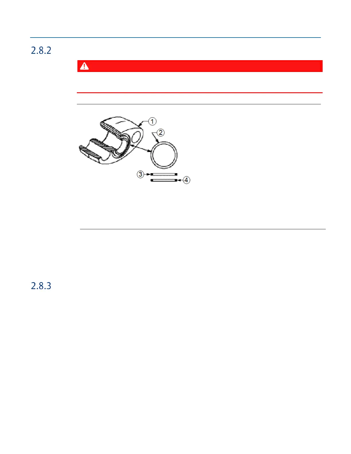
Whenever the flange or adapters are removed, visually inspect the O-rings.
2.
Replace the O-rings if there are any signs of damage, such as nicks or cuts.
3.
If the O-rings are replaced, re-torque the flange bolts and alignment screws after installation
to compensate for seating of the O-rings.
Pole Mounting – Aluminum Enclosure
Refer to Figure 2-15 during the mounting procedure.
1.
Apply Loctite
®
222 Low Strength Purple Threadlocker sparingly to threads of head cap screws
(Item 2).
2.
Attach pole mounting brackets (Item3) to enclosure using head cap screws (Item 2) and hex
nuts (Item 1). Torque hex nuts to 30 in-lbs (3.4 N m).
3.
Apply Loctite 222 Threadlocker sparingly to threads of U-bolts (Item 4).
4.
Use U-bolts (Item 4) to mount enclosure to pole using hex nuts (Item 1). Torque hex nuts to
30 in-lbs (3.4 N m).
 Loading...


