Emerson FB2200 Flow Computer Instruction Manual
D301784X012
March 2019
76 I/O Configuration and Wiring
3.5.1 PI Wiring
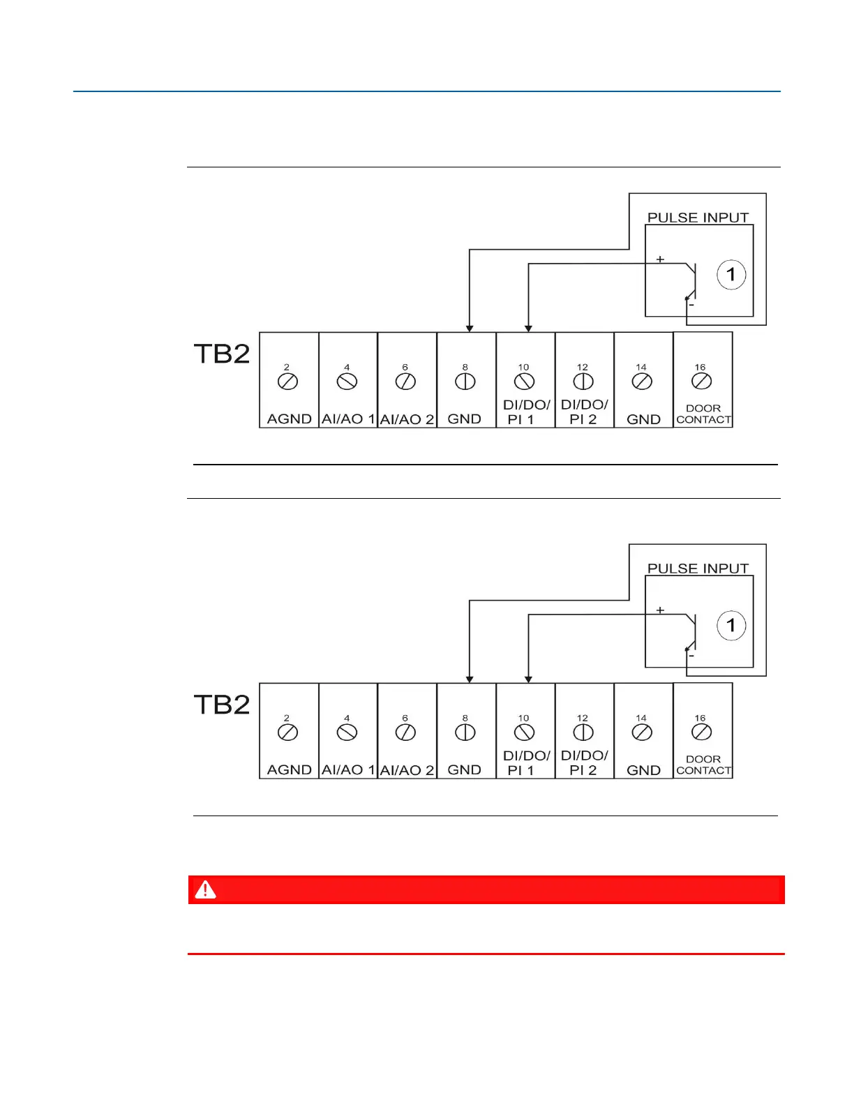
The following diagrams show how to wire the pulse inputs.
Figure 3-11. PI Wiring: Base I/O (DI/DO/PI1 & DI/DO/PI2)
Open Drain Type or Open Collector Device (Externally Powered)
Figure 3-12. PI Wiring: Optional 8-channel Expansion I/O Module (ISO DI/DO/PI3,4,5,6) and
Optional 6-channel Expansion I/O Module (ISO DI/DO/PI7,8)
Open Drain Type or Open Collector Device (Externally Powered)
3.6 Connecting the RTD/PRT
EXPLOSION HAZARD: Ensure the area in which you perform this operation is non-hazardous.
Performing this operation in a hazardous area could result in an explosion.
 Loading...


