Quick Start
Commissioning
76 Digistart IS User Guide
www.controltechniques.com Issue: 4
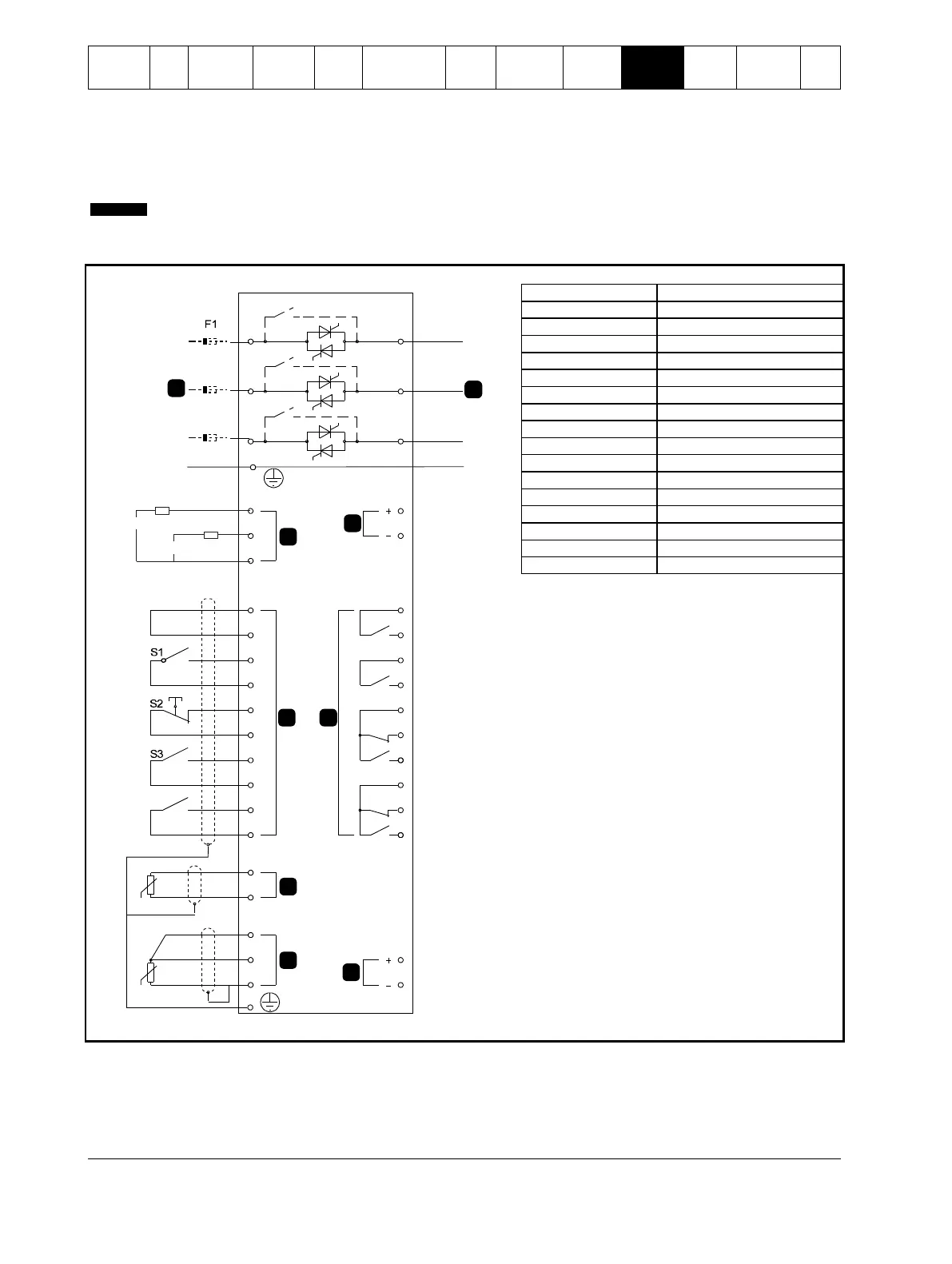
10.3 Emergency run operation
In normal operation the Digistart IS is controlled via a remote two wire signal (terminals DI2, +24V).
Emergency Run is controlled by a two wire circuit connected to Input A (terminals DI4, +24V). Closing Input A causes the Digistart
IS to run the motor and ignore certain trip conditions.
Although the Emergency Run satisfies the functionality requirements of Fire Mode, Control Techniques does not
recommend its use in situations that require testing and/or compliance with specific standards as it is not certified.
Figure 10-3 Emergency run operation
08535.A
7
6
5
4
3
2
1
8
9
RLC3
COM3
COM1
RLO1
+24V
0V
RLO2
COM2
RLO3
AO1
0V
COM4
RLC4
RLO4
TH2
TH1
DI2
+24V
DI3
+24V
DI4
+24V
+24V
+24V
DI5
PT4
PT5
PT3
CSR
CSL
CSH
DI1
E
110-210 VAC
+10%
-15%
220-440 VAC
+10%
-15%
6/T3
2/T1
4/T2
5/L3
3/L2
1/L1
E
Semiconductor fuses (optional)
Parameter settings:
Pr 3A Input A Function
Select 'Emergency Run' - assigns Input A for Emergency Run function.
Pr 15B Emergency Run
Select 'Enable' - Enables Emergency Run mode
 Loading...


