Quick Start
Commissioning
78 Digistart IS User Guide
www.controltechniques.com Issue: 4
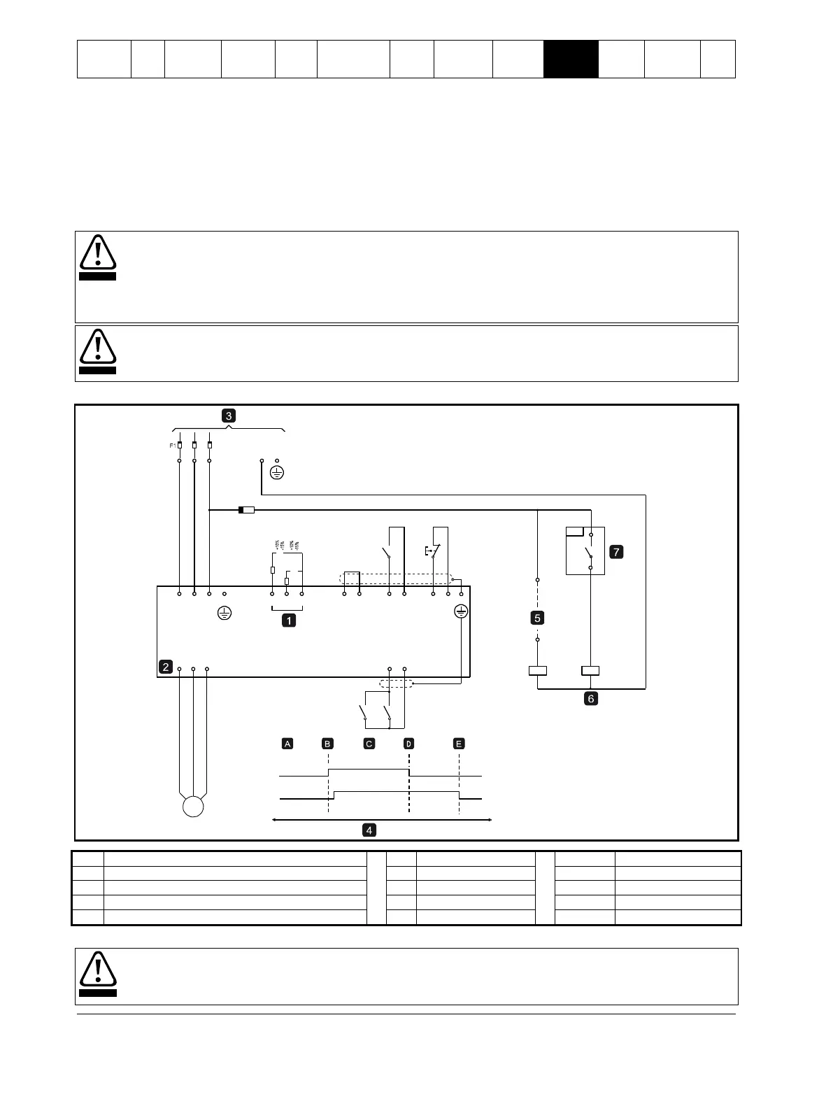
10.5 DC brake with external zero speed sensor
For loads which may vary between braking cycles, there are benefits in using an external zero-speed sensor to interface with the
Digistart IS for brake shut-off. This control method ensures that the Digistart IS braking will always shut off when the motor has
reached a standstill, thus avoiding unnecessary motor heating.
The following schematic diagram shows how you can use a zero-speed sensor with the Digistart IS to turn the brake function off at
motor standstill. The zero-speed sensor (A2) is often referred to as an under-speed detector. Its internal contact is open at
zero-speed and closed at any speed above zero-speed. Once the motor has reached a standstill, the Digistart IS will go into
Emergency Stop mode and remain in this state until the next start command is given (i.e. next application of KA1).
The Digistart IS must be operated in remote mode and Pr 3A Input A Function must be set to emergency stop.
If the brake torque is set too high, the motor will stop before the end of the brake time and the motor will suffer
unnecessary heating which could result in damage. Careful configuration is required to ensure safe operation of the
starter and motor.
A high brake torque setting can result in peak currents up to motor DOL being drawn while the motor is stopping. Ensure
protection fuses installed in the motor branch circuit are selected appropriately.
Brake operation causes the motor to heat faster than the rate calculated by the motor thermal model. If you are using
brake, install a motor thermistor or allow sufficient restart delay (Pr 6G).
Figure 10-5 DC brake with external zero speed sensor
Emergency stop mode (shown on starter display)
For details on configuring DC Brake, see Brake on page 41.
When using DC brake, the mains supply must be connected to the soft starter (input terminals L1, L2, L3) in positive
phase sequence and Pr 5D Phase Sequence must be set to Positive only.
F1
5/L3
3/L21/L1
N
KA1
E
2/T1
SH
DI1 +24
KA1
KA2
KA1
KA2
KA2KA1
A2
08921.B
V
+24
V
+24
VDI2 DI3
C SLC SRC
DI4
+24
V
E
5/L33/L21/L1
4/T2 6/T3
10-210VAC
220-440VAC
1
E
M3
 Loading...


