
 Loading...


Do you have a question about the Emerson FB1200 and is the answer not in the manual?
| Brand | Emerson |
|---|---|
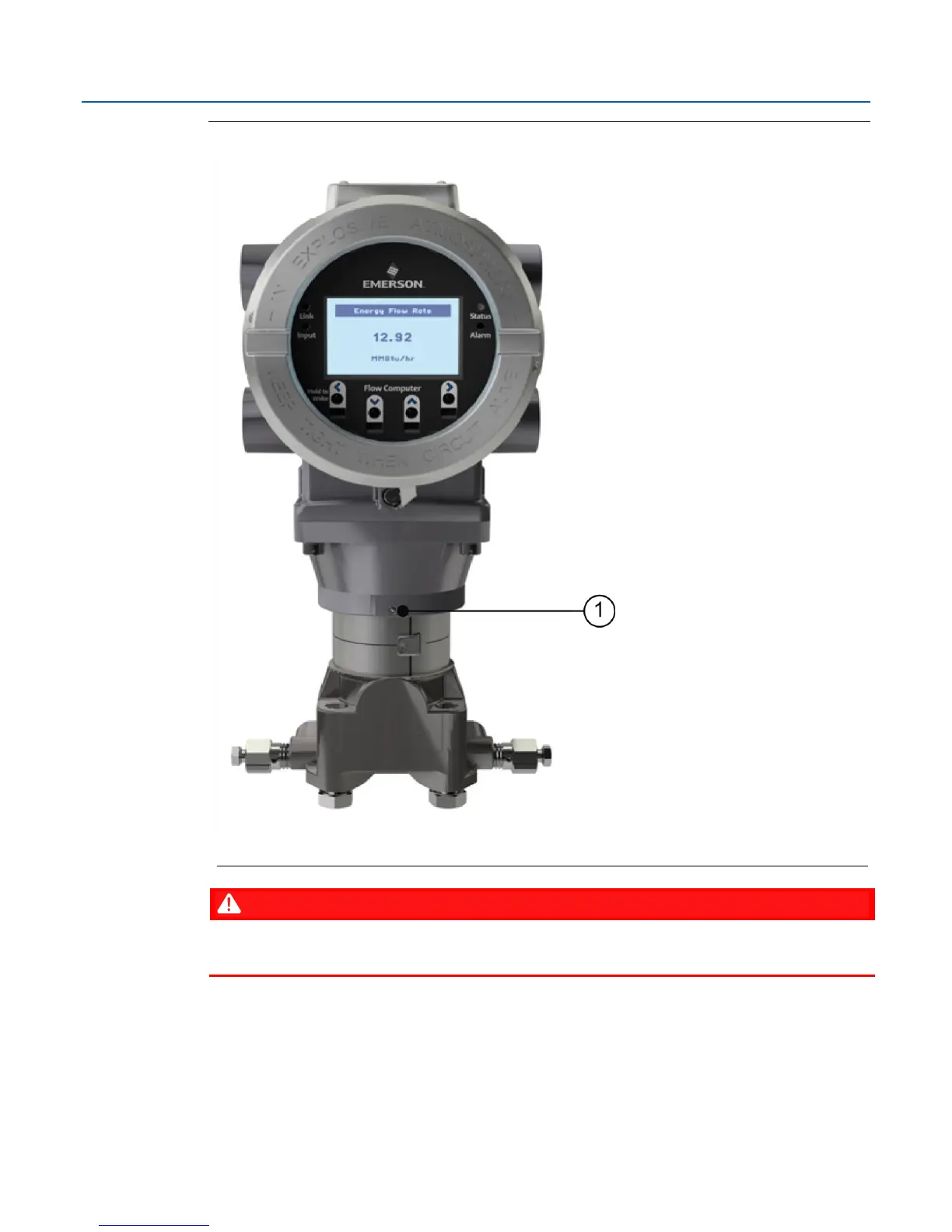
| Model | FB1200 |
| Category | Measuring Instruments |
| Language | English |
Explains safety labels to identify potential hazards and their meaning.
Highlights the key features and capabilities of the FB1200 Flow Computer.
Details available FB1200 Flow Computer models, with and without integrated sensors.
Provides details on the Central Processing Unit (CPU) and its operating specifications.
Details the explosion-proof enclosure, its construction, and components.
Details retaining clamps and methods for tamper-resistant seals on end caps.
Describes the Input/Output (I/O) capabilities, channels, and configurations.
Outlines the available power sources for the flow computer, including DC and battery.
Details serial and Ethernet communication ports, protocols, and connections.
Explains the Human-Machine Interface (HMI) module, its display, buttons, and operation.
Provides information on the optional FBxWifi feature for wireless laptop connectivity.
Introduces the FBxConnect software for configuration, diagnostics, and updates.
States compliance with RoHS2 EU Directive 2011/65/EU.
Details design for hazardous location operation and certifications.
Details the environmental operating parameters, such as temperature and humidity.
Lists the necessary tools and equipment for installation and servicing the device.
Provides guidelines for selecting an appropriate installation location for the device.
Presents best practices for wiring connections, including wire gauge, shielding, and termination.
Provides procedures for removing and replacing the front and rear end caps.
Provides instructions for mounting the enclosure, including bolting, O-rings, and kits.
Details procedures for connecting the ground wire to the device and earth ground.
Shows the terminal plate layout and descriptions for power and I/O connections.
Explains Low Power Mode and Standard Power Mode operations and their power consumption.
Provides instructions for connecting external DC supply or battery/solar panel power.
Guides installation of the solar panel, including hardware, mounting, wiring, and tilt.
Details procedures for connecting serial ports (COM1-3) and the Ethernet port.
Details on configuring and wiring analog input (AI) channels.
Details on configuring and wiring analog output (AO) channels.
Provides information on configuring and wiring digital input (DI) channels.
Provides information on configuring and wiring digital output (DO) channels.
Provides instructions for configuring and wiring pulse input (PI) channels.
Provides detailed instructions for wiring Resistance Temperature Detectors (RTDs).
Guides connecting an external transmitter (e.g., Rosemount 4088B) for a second meter run.
Describes the procedures for powering the flow computer up and down.
Details methods for establishing communications with SCADA, laptops, or wirelessly.
Explains how to interact with the flow computer using its Human-Machine Interface (HMI) module.
Outlines procedures for returning the unit for authorized repair services.
Explains the meaning of different status LED states, colors, and sequences.
Details the function and operation of the unit's switches and push buttons.
Provides instructions for safely removing and replacing the HMI module.
Details the steps for replacing the main battery pack of the device.
Provides procedures for removing and replacing the SRAM backup coin cell battery.
Guides the process of updating the flow computer's system firmware.
Outlines conditions and limitations for ATEX flame-proof applications.


