DO Function Block
December 2009
4-151
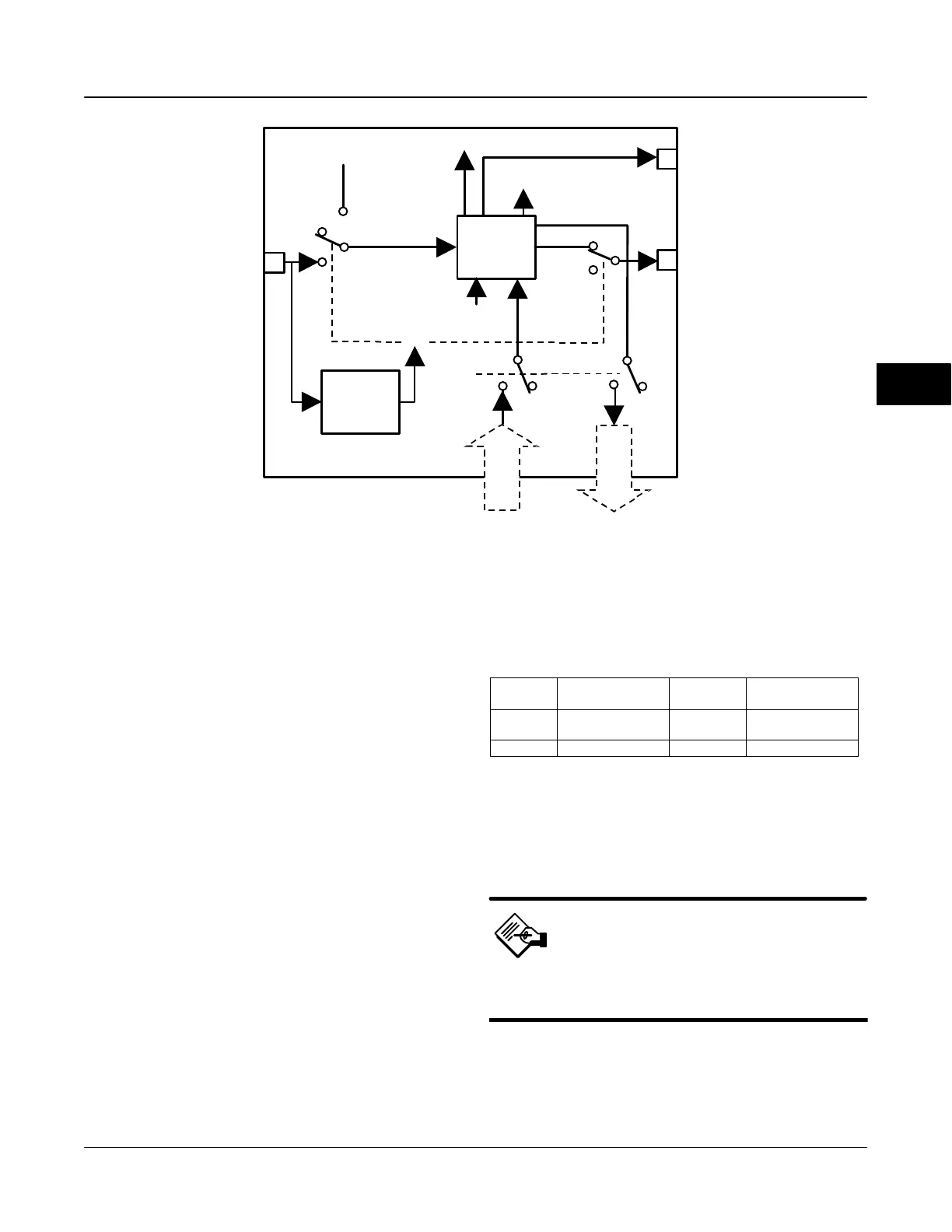
CAS_IN_D
IO_OPTS
RCAS_IN_D
SIMULATE_D
MODE
CHANNEL
TRANSDUCER
BLOCK
SP_D
PV_D
RCAS_OUT_D
OUT_D
BKCAL_OUT_D
READBACK_D
CONVERT AND
STATUS
CALCULATION
SHED MODE
Figure 4-29. Discrete Output Function Block Schematic
TRANSDUCER
BLOCK FEEDBACK
I/O Selection
To select the I/O associated with the discrete output,
configure the value of the CHANNEL [18] parameter.
Table 4-68 lists the valid Channel selections for the
DO block.
Setting the Output
To set the output for the DO block, you must first set
the mode to define the manner in which the block
determines its set point and output. In Cascade mode,
the set point equals the input value at the CAS_IN_D
[17] parameter. In Automatic or Manual mode, the set
point must be entered manually by the user. For
Automatic, the value must be written to the SP_D [8]
parameter and for Manual, the value must be written
to OUT_D [9]. In Remote Cascade mode, the set point
is determined by a host computer that is writing to the
RCAS_IN_D [22] parameter. Table 4-69 lists discrete
states used by the digital valve controller for the set
point.
To further customize the output, configure the
following supported I/O options: SP tracks PV in Man,
Table 4-68. Channel Selections for the Discrete Output
Function Block
Selection
Transducer Block
Parameter
Transducer
block Index
Description
22 SETPOINT_D 32
Discrete Valve
Control
0 − − Uninitialized
SP tracks PV in LO, SP Track retained target in Man
or LO, Fault State to Value, Use Fault State value on
restart, Target to Man if Fault State activated, and US
PV for BKCAL_OUT.
Note
You can configure the supported I/O
options in Out of Service mode only.
The SP_PV Track in Man option permits the set point
to track the process variable when the block is in
Manual mode. With this option enabled, the set point
(SP_D [8]) becomes a copy of the process variable
4

 Loading...


