DVC6000f Digital Valve Controllers
December 2009
5-6
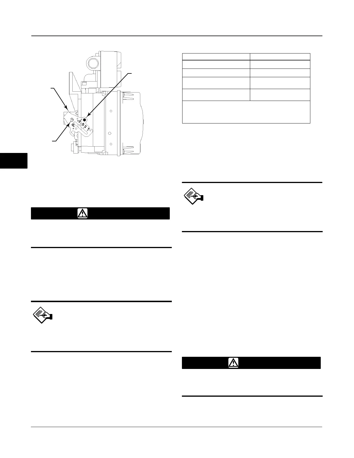
Figure 5-3. FIELDVUE DVC6010f Digital Valve Controller
Showing Feedback Arm in Position for Travel Sensor
Adjustment
Feedback Arm
(key 79)
A
B
Travel
Sensor
Shaft
Alignment Pin
(key 46)
A7023 / IL
WARNING
Failure to remove air pressure may
cause personal injury or property
damage from bursting parts.
2. As shown in figure 5-3, align the feedback arm (key
79) with the housing by inserting the alignment pin
(key 46) through the hole marked “A” on the feedback
arm. Fully engage the alignment pin into the tapped
hole in the housing.
Note
The alignment pin (key 46) is
stored inside the digital valve
controller housing.
3. Loosen the screw that secures the feedback arm to
the travel sensor shaft. Position the feedback arm so
that the surface of the feedback arm is flush with the
end of the travel sensor shaft.
4. Connect a Fieldbus power source and the Field
Communicator to the instrument LOOP − and LOOP +
terminals.
Table 5-1. Travel Sensor Counts
Digital Valve Controller Travel Sensor Counts
DVC6010f / DVC6015
3300 $ 700 counts
DVC6020f / DVC6025
8600 $ 700 counts
DVC6030f
(1)
/ DVC6035
(2)
Counterclockwise shaft rotation
3100 $ 700 counts
DVC6030f
(3)
/ DVC6035
(2)
Clockwise shaft rotation
13 400 $ 700 counts
1. Refer to figure 2-9 to determine the desired starting position for the
DVC6030f based on counterclockwise potentiometer shaft rotation.
2. Refer to figure 2-14 to determine the desired starting position for the
DVC6035 based on potentiometer shaft; counterclockwise or clockwise.
3. Refer to figure 2-10 to determine the desired starting position for the
DVC6030 based on clockwise potentiometer shaft rotation.
5. Before beginning the travel sensor adjustment, set
the Transducer Block Mode to Manual and the
protection to None.
6. From the Calibrate menu, select Travel Sensor
Adjust. Follow the prompts on the Field Communicator
display to adjust the travel sensor counts to the value
listed in table 5-1.
Note
In the next step, be sure the feedback
arm surface remains flush with the end
of the travel sensor shaft.
7. While observing the travel sensor counts, tighten
the screw that secures the feedback arm to the travel
sensor shaft. Be sure the travel sensor counts remain
within the tolerances listed in table 5-1. Paint the
screw to discourage tampering with the connection.
8. Disconnect the Field Communicator and Fieldbus
power source from the instrument.
9. Remove the alignment pin and store it in the
instrument housing.
10. Install the digital valve controller on the actuator.
DVC6020f and DVC6025 Digital Valve
Controllers
1. Remove supply air and remove the instrument from
the actuator.
WARNING
Failure to remove air pressure may
cause personal injury or property
damage from bursting parts.
2. See figure 5-5 for parts identification. Disconnect
the bias spring (key 82) from the feedback arm
5

 Loading...


