DVC6000f Digital Valve Controllers
December 2009
2-20
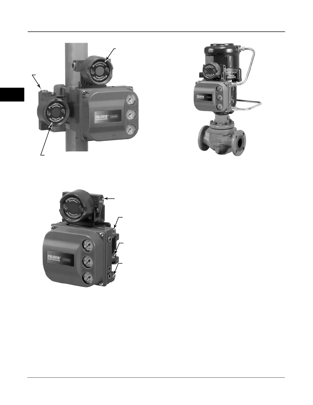
OUTPUT A
CONNECTION
SUPPLY
CONNECTION
OUTPUT B
CONNECTION
1/2 NPT
CONDUIT
CONNECTIONS
(BOTH SIDES)
W7963-1FF
NOTE:
PNEUMATIC CONNECTIONS APPLICABLE TO BOTH VALVE-MOUNTED
INSTRUMENTS AND DVC6005f BASE UNIT.
Figure 2-16. Pressure Connections
LOOP CONNECTIONS
TERMINAL BOX
FEEDBACK CONNECTIONS
TERMINAL BOX
1/2 NPT
CONDUIT
CONNECTION
DVC6005f BASE UNIT
W8371-1-FF
VALVE-MOUNTED
INSTRUMENT
Single-Acting Actuators
When using a single-acting direct digital valve
controller (relay A or C) on a single-acting actuator
connect OUTPUT A to the actuator pneumatic input.
Figure 2-17. FIELDVUE DVC6010f Digital Valve Controller
Mounted on Fisher 585C Piston Actuator
W9132-1
When using a single-acting reverse digital valve
controller (relay B) on a single-acting actuator connect
OUTPUT B to the actuator diaphragm casing.
Double-Acting Actuators
DVC6000f digital valve controllers on double-acting
actuators always use relay A. With no instrument
Fieldbus power (Zero Power Condition), OUTPUT A is
at 0 pressure and OUTPUT B is at full supply pressure
when the relay is properly adjusted.
To have the actuator stem retract into the cylinder with
Zero Power Condition, connect OUTPUT A to the
upper actuator cylinder connection. Connect OUTPUT
B to the lower cylinder connection. Figure 2-17 shows
the digital valve controller connected to a
double-acting piston actuator.
To have the actuator stem extend from the cylinder
with Zero Power Condition, connect OUTPUT A to the
lower actuator cylinder connection. Connect OUTPUT
B to the upper cylinder connection.
Special Construction to Support Logic
Solver Initiated Solenoid Valve Health
Monitoring
In single-acting actuator applications with a solenoid
valve installed, the DVC6000f can be configured to
monitor the health of the solenoid valve test, which is
initiated by the Logic Solver. This is accomplished by
connecting the unused output port B from the
DVC6000f to the pneumatic monitoring line between
2

 Loading...


