Installation
December 2009
2-7
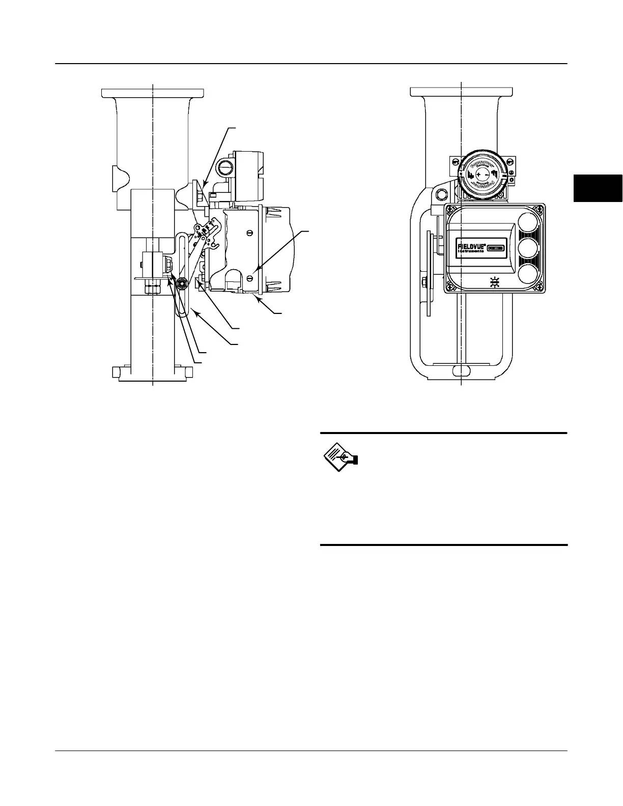
Figure 2-1. FIELDVUE DVC6010f Digital Valve Controller Mounted on Sliding-Stem Actuators with up to 2 Inches Travel
29B1674-A / DOC
29B3403-A
CAP SCREW, FLANGED
MACHINE SCREW
SHIELD
ADJUSTMENT ARM
CONNECTOR ARM
CAP SCREW
PLAIN WASHER
Mounting Guidelines
DVC6010f on Sliding-Stem Actuators Up
to 102 mm (4 Inches) of Travel
If ordered as part of a control valve assembly, the
factory mounts the digital valve controller on the
actuator, makes pneumatic connections to the
actuator, sets up, and calibrates the instrument. If you
purchased the digital valve controller separately, you
will need a mounting kit to mount the digital valve
controller on the actuator. See the instructions that
come with the mounting kit for detailed information on
mounting the digital valve controller to a specific
actuator model.
The DVC6010f digital valve controller mounts on
sliding-stem actuators with up to 102 mm (4 inch)
travel. Figure 2-1 shows a typical mounting on an
actuator with up to 51 mm (2 inch) travel. Figure 2-2
shows a typical mounting on actuators with 51 to 102
mm (2 to 4 inch) travel. For actuators with greater than
102 mm (4 inch) travel, see the guidelines for
mounting a DVC6020f digital valve controller.
Note
Do not use the stainless steel
DVC6010fS in high vibration service
where the mounting bracket uses
standoffs (spacers) to mount to the
actuator.
Refer to the following guidelines when mounting on
sliding-stem actuators with up to 4 inches of travel.
Where a key number is referenced, refer to
figure 8-2.
1. Isolate the control valve from the process line
pressure and release pressure from both sides of the
valve body. Shut off all pressure lines to the actuator,
releasing all pressure from the actuator. Use lock-out
procedures to be sure that the above measures stay in
effect while you work on the equipment.
2. Attach the connector arm to the valve stem
connector.
3. Attach the mounting bracket to the digital valve
controller housing.
2

 Loading...


