Basic Setup
December 2009
3-3
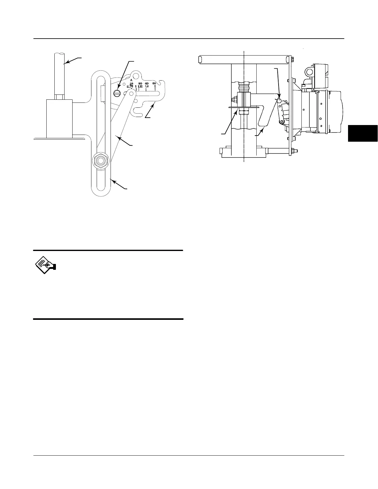
ACTUATOR
STEM
TRAVEL SENSOR SHAFT
FEEDBACK ARM
CONNECTOR ARM
ADJUSTMENT ARM
Figure 3-1. Feedback Connection for Typical Sliding-Stem
Actuator (Up to 4 inch Travel)
A6536-1 / IL
Note
If reverse acting relay B is used, you
must manually set the Relay Type
(BASIC_SETUP.RELAY_TYPE [42.5]) to
B. This will not be set during Device
Setup.
1. Select whether Travel, Travel with Pressure
fallback (auto recovery or manual recovery) or
Pressure Control is desired. Refer to page 4-25 for
additional information.
2. Enter the pressure units:kPa, bar, psi, inHg, inH
2
O,
or kg/cm
2
.
3. Enter the maximum instrument supply pressure
and output pressure range (if required).
4. Enter the manufacturer of the actuator on which
the instrument is mounted. If the actuator
manufacturer is not listed, select Other.
5. Enter the actuator model or type. If the actuator
model is not listed, select Other.
6. Enter the actuator size.
CAM
ROLLER
29B1665-A / DOC
STEM
CONNECTOR
Figure 3-2. Feedback Connection for Typical Long-
Stroke Sliding-Stem Actuator (4 to 24 Inches Travel)
7. Indicate whether a Volume Booster is being used.
8. Specify if factory defaults should be used for basic
setup. If you select YES for factory default, the Field
Communicator sets the setup parameters to the
values listed in table 3-1. If you select NO for the
factory defaults, the setup parameters listed in the
table remain at their previous settings.
Typically Device Setup determines the required setup
information based upon the actuator manufacturer and
model specified. However, if you enter other for the
actuator manufacturer or the actuator model, then you
will be prompted for setup parameters such as:
Actuator Style—Select spring & diaphragm,
piston double-acting without spring, piston
single-acting with spring, piston double-acting with
spring.
Valve Style—Select the valve style, rotary or
sliding-stem.
Zero Power Condition—Identifies whether the
valve is fully open or fully closed when the instrument
is outputing the smallest signal to the I/P module.
Typically, this setting matches the valve position when
the instrument is not powered. For instruments with
relay A or C, if increasing air pressure at output A
causes the valve to open, the Zero Power Condition is
Closed. If the valve closes under these conditions, the
Zero Power Condition is Open. For instruments with
relay B, if decreasing air pressure at output B causes
the valve to open, the Zero Power Condition is Closed.
If the valve closes under these conditions, the Zero
Power Condition is Open.
3

 Loading...


