Quick Start Guide
D103556X012
DVC6200 Digital Valve Controllers
July 2017
28
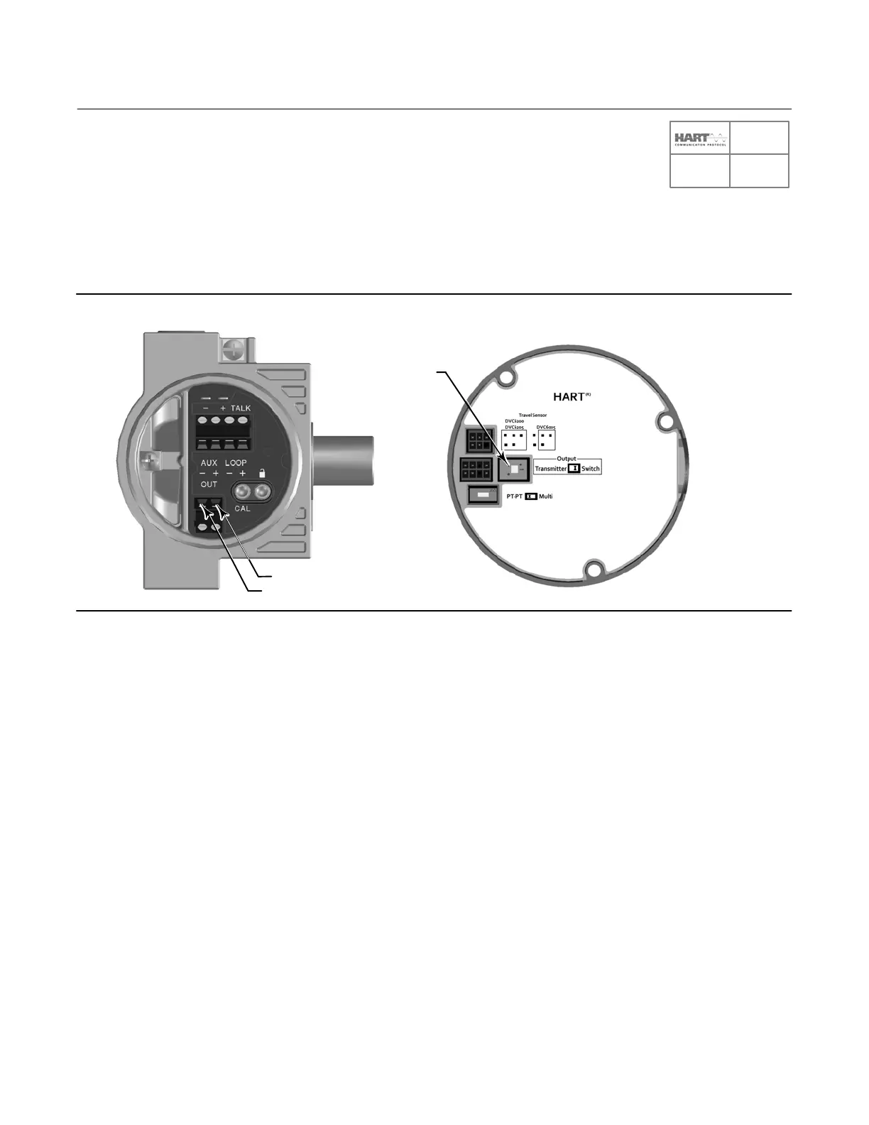
Position Transmitter or Discrete Switch
The DVC6200 HART communicating device has an optional output circuit that can be configured as a 420 mA
position transmitter or a discrete switch. Configuration of the output circuit requires the proper DIP switch electrical
setting on the main electronics board (figure 22) and also must be enabled with a user interface tool. The DIP switch
electrical setting is preconfigured at the factory when ordered properly.
Figure 22. OUTPUT Connections and Transmitter / Switch Settings
OUTPUT+
OUTPUT-
DIP SWITCH FOR
TRANSMITTER/SWITCH
SELECTION
X0432
X0430
The position transmitter circuit derives its operating power from the control system input channel in the same manner
as a 2wire transmitter.
The discrete switch is a solid state circuit (1amp maximum) which opens and closes based on a user configurable trip
point. The trip point can be based on valve travel anywhere within the calibrated travel range, or based on a device
alert. In order for the switch output to function, the digital valve controller must be powered. If power is lost, the
switch will always go to the open state. The output circuit, whether operating as a transmitter or switch, is galvanically
isolated from the position control loop circuit such that different ground references between the 2 circuits are
allowed.
Wire the OUTPUT terminals as follows (refer to figure 23):
1. Route the field wiring into the terminal box through the conduit connection.
2. When applicable, install conduit using any local and national electrical codes that apply to the connection.
3. Connect the control system input channel positive wire to the OUT (+) terminal. Connect the control system input
channel negative wire to the OUT () terminal.
4. Replace and hand tighten the cover on the terminal box.
5. For applications that require Remote Feedback Mounting (page 30) and/or a THUM Adapter (page 32), proceed to
the appropriate page. For DVC6200 SIS applications proceed to Special Instructions for DVC6200 SIS on page 35.
Otherwise, proceed to Step 4—Configure the Digital Valve Controller on page 33.
SIS

 Loading...


