7
2.5.4 Control Circuit Wiring (FPCSK)
2.5.4.1 Analog Output
A 0-10 Vdc analog output signal is available by connecting to Commander HSK control
terminals B1 (+) and T1 (-). The default is output frequency.
2.5.4.2 Digital Input
The Electronic bypass combines digital inputs from the Commander HSK inverter and the
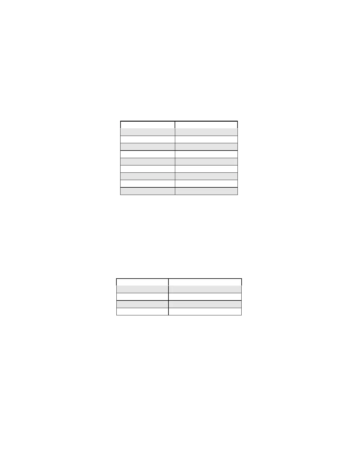
Electronic bypass control board to allow maximum flexibility. As per the following table, the
Electronic bypass control board provides eight (8) digital inputs.
Terminal No. Description
TB2-3 Safety (NC)
TB2-4 Reset
TB2-5 Automatic Run
TB2-6 Fire (NC)
TB3-1 Remote Bypass
TB3-2 Remote VFD
TB3-3 Damper Feedback
TB3-4 Fireman’s Override
TB2-8 &TB4-1,2,3 Common
All digital inputs are dry contacts (voltage free).
2.5.4.3 Digital / Relay Outputs
There are four (4) Form A relay outputs rated 125 Vac, 0.5 A on the Electronic bypass control
board.
Terminal No. Description
TB1-1 & TB1-2 Power On
TB1-3 & TB1-4 Fault
TB1-5 & TB1-6 Damper actuator
TB1-7 & TB1-8 Automatic mode selected

 Loading...


