11
2.7.1 Check #1: Rotation on VFD power
Place the VFD package in HAND (local) control by pressing the VFD and
HAND push buttons of the Electronic bypass keypad. The VFD, HAND, input
and output contactor LEDs will be illuminated. The VFD must be started and
stopped by the start/stop buttons on the VFD keypad. Use the up arrow on the
VFD Keypad to increase the speed reference of the VFD or the down arrow on
the VFD Keypad to decrease the speed reference of the VFD. Note the
direction of rotation as the motor shaft begins to rotate as compared to the
required rotation direction.
To stop the VFD, press the OFF/RESET push button.
2.7.2 Check #2: Rotation on Bypass power
NOTE: This operation will start the motor across-the-line. Place the Electronic
bypass in the BYPASS mode by pressing the BYPASS pushbutton on the
Electronic bypass keypad. The BYPASS LED will light.
Press the HAND button on the Electronic bypass keypad. This will start the
motor across
the line. Check motor rotation.
Quickly stop the motor by pressing the OFF/RESET push button.
Note the direction of rotation as the motor shaft begins to rotate as compared
to the required rotation direction.
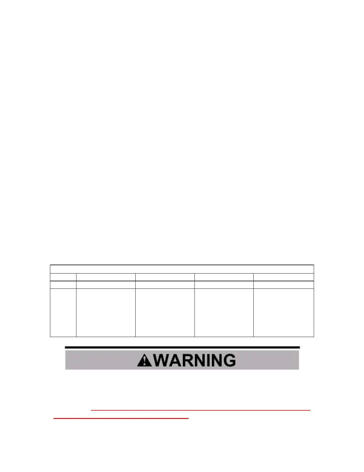
Change the appropriate leads as noted in the following table.
Motor Rotation Correction
VFD Correct Correct Incorrect Incorrect
Bypass Correct Incorrect Correct Incorrect
Action
No Action.
Change any two
power leads at input
disconnect.
Change any two
leads at input at
input disconnect,
and change any two
leads at the output
of the motor
overload.
Change any two
leads at output of
motor overload.
There is no standard for the rotational direction of an induction motor based
on the motor lead markings. This, plus the uncertainty of the phase rotation
of the utility power being applied to the Electronic bypass package
terminals, requires that the motor rotation direction be checked and be
correct in both VFD and Bypass modes. Failure to confirm rotation may cause
severe damage to the Electronic bypass package, motor or the driven equipment.

 Loading...


