10
2.5.6 Grounding
Never ground the Electronic bypass package in common with welding machines,
motors, or other high current electrical equipment. Run all ground wires in a
separate conduit.
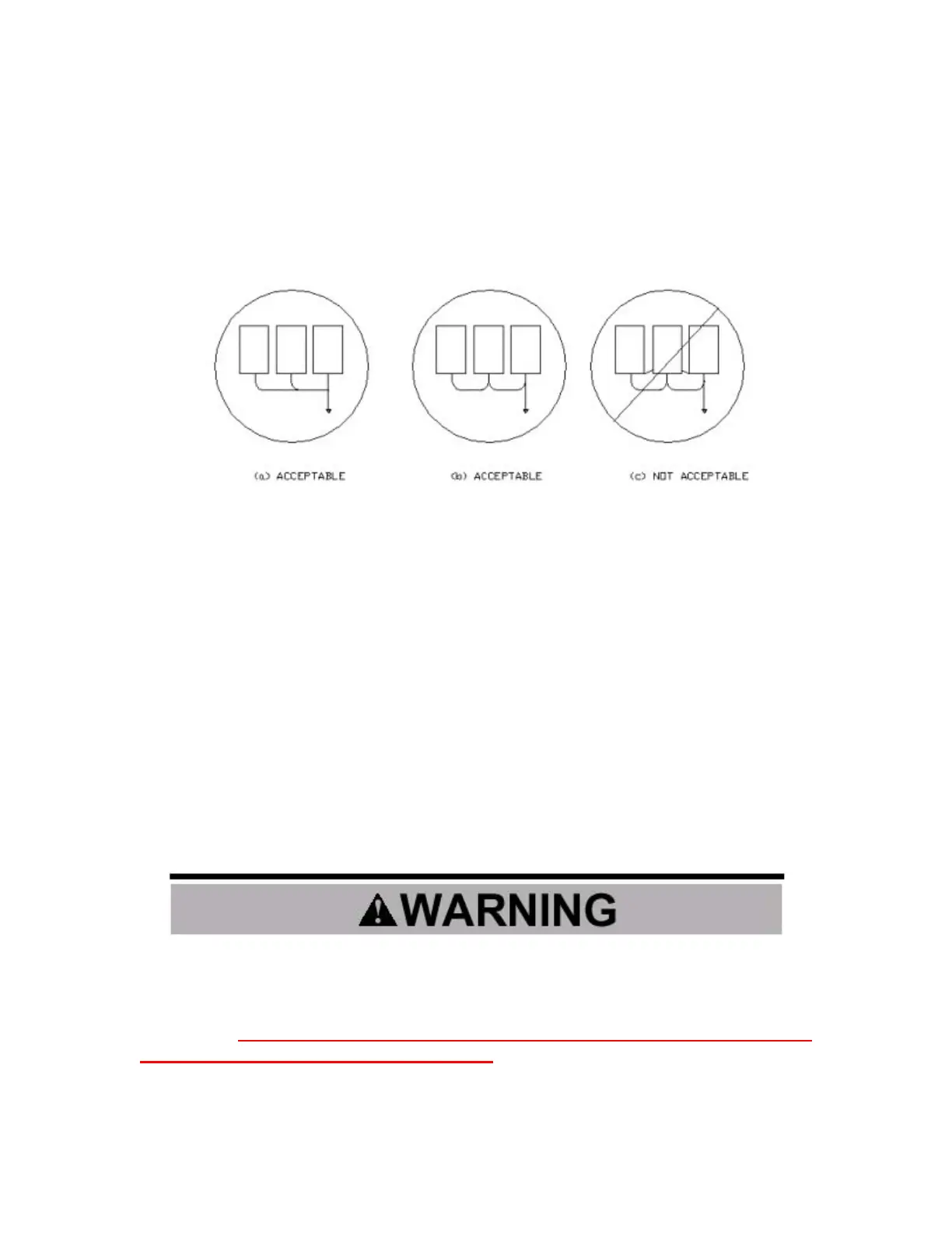
When using several Electronic bypass packages side by side, ground as shown
below.
2.6 Inspection
After all wiring is completed, verify that:
1 – All wiring is installed.
2 – Excess screws, metal filings, and wire clippings are removed from inside
the unit(s).
3 – Screws and fasteners are securely tightened.
4 – Exposed wiring has no contact with other wiring or terminals.
2.7 Checking Motor Rotation
Before attempting a trial operation of the Electronic bypass package, insure that
the enclosure door is securely closed. Also, insure all personnel are clear of the
connected load as this operation will energize and rotate the motor. After applying
3 phase power to the Electronic bypass package insure that the MAIN POWER
LED is illuminated. If any alarms are illuminated refer to chapter 6 for explanation.
There is no standard for the rotational direction of an induction motor based
on the motor lead markings. This, plus the uncertainty of the phase rotation
of the utility power being applied to the Electronic bypass package
terminals, requires that the motor rotation direction be checked and be
correct in both VFD and Bypass modes. Failure to confirm rotation may cause
severe damage to the Electronic bypass, motor or its driven equipment.

 Loading...


