8
2.5.4.4 Internal Control Wire Connections
There are factory connections between the Electronic bypass control board and
the Commander HSK inverter. These connections are made at the factory and are
for reference only. Do not change this wiring as it will cause the Electronic bypass
to operate improperly or not at all.
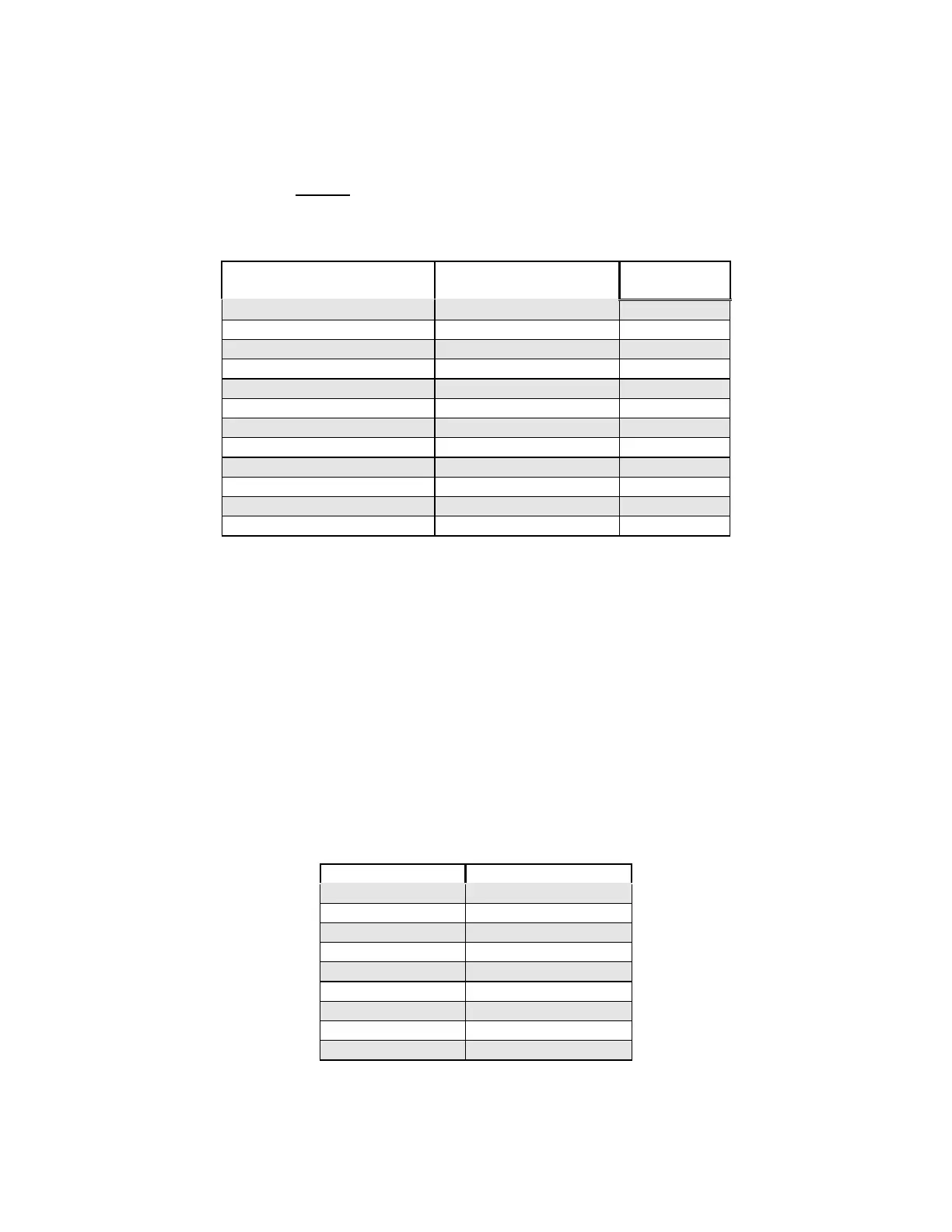
Electronic bypass control
Board
FPCSK
Wire
number
J11 – 1 Motor overload relay 12
J11 – 2 T5 11
J11 – 3 T1 16
J11 – 4 B7 10
J11 – 5 N/C N/A
J11 – 6 B5 8
J11 – 7 B6 9
J10 - 1 Input Contactor 5
J10 – 2 Bypass Contactor 4
J10 - 3 Output Contactor 3
J10 - 4 115 Vac (Neutral) 2
J10 - 5 115 Vac (Hot) 1
2.5.5 Control Circuit Wiring (FPCBA)
2.5.5.1 Analog Output
A 0-10 Vdc analog output signal is available by connecting to Affinity control
terminals 9 (+) and 11 (-). The default is output frequency.
2.5.5.2 Digital Input
The Electronic bypass combines digital inputs from the Affinity inverter and
the Electronic bypass control board to allow maximum flexibility. As per the
following table, the Electronic bypass control board provides eight (8) digital
inputs.
Terminal No. Description
TB2-3 Safety (NC)
TB2-4 Reset
TB2-5 Automatic Run
TB2-6 Fire (NC)
TB3-1 Remote Bypass
TB3-2 Remote VFD
TB3-3 Damper Feedback
TB3-4 Fireman’s Override
TB2-8 &TB4-1,2,3 Common
All digital inputs are dry contacts (voltage free).

 Loading...


