Application Guide Chapter 4
GFK-2928C Oct 2019
Toolchest Components 12
4.2 Adding Dual Bus Logic
In the ladder block named _Main, insert a new row at the beginning of the program.
While holding down the Ctrl-key, drag the program block named BUSSES and place it into
the first rung. This will create a new instance of the block. It will require a name: enter
GBusses for the name.
Zoom into the ladder block named BUSSES. Note that the program block already contains
multiple rungs of logic. Program blocks in these rungs perform the following:
INIT_GB00 This structured text block defines the parameters for a dual bus (the
instance is named IGB00 for “Initialize Genius Bus 00”). The block must be
edited to match the specific design characteristics of the system.
DBUS This ladder block maps the discrete and analog inputs for the dual bus (the
instance is named DB00). It does not require additional editing.
AUTO_SW This ladder block provides a simple automatic role switching method (the
instance is named Aut_Sw). It does not require additional editing, but you
may wish to modify or enhance the PLC failover operation.
The logic at this point is enough to service one pair of dual busses. If there are more dual
busses, then additional rungs will be required.
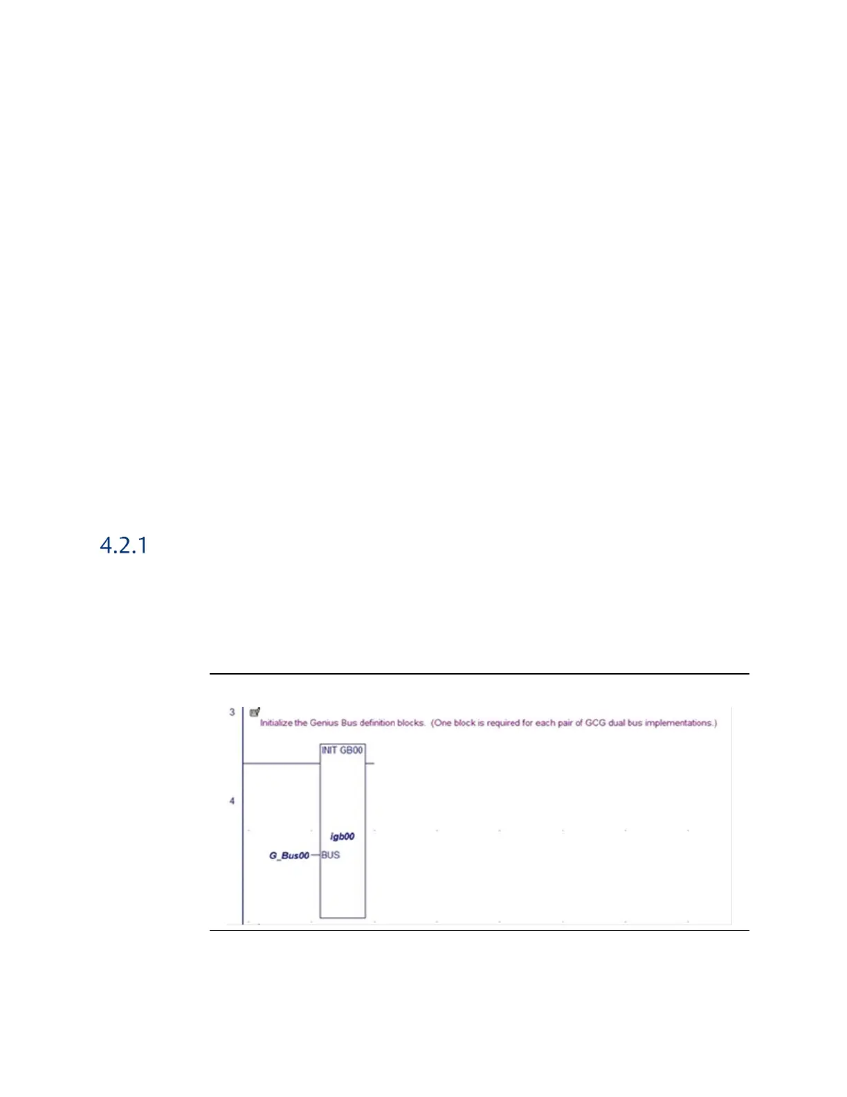
Dual Bus Parameters
Select the function block in the rung that immediately follows the comment rung
containing the text “Initialize the Genius Bus definition blocks”. Double-click on the function
block to zoom into and explore the logic that is contained in the block. This block will require
editing in order to enter parameters that define the operation and devices on the
corresponding dual bus.
Figure 10: Edit Genius Bus Definition Block(s)
Note the variable on the left side of the function block. This a “user-defined type” that
contains the detailed information specific to the dual bus. When the function block
executes, the user-supplied entries present in the structured text are assigned to the
members of the bus variable.

 Loading...


