Application Guide Chapter 5
GFK-2928C Oct 2019
PLC Hardware Configuration 21
5.6 Configure the Genius Communication Gateway
Modules
Settings Tab
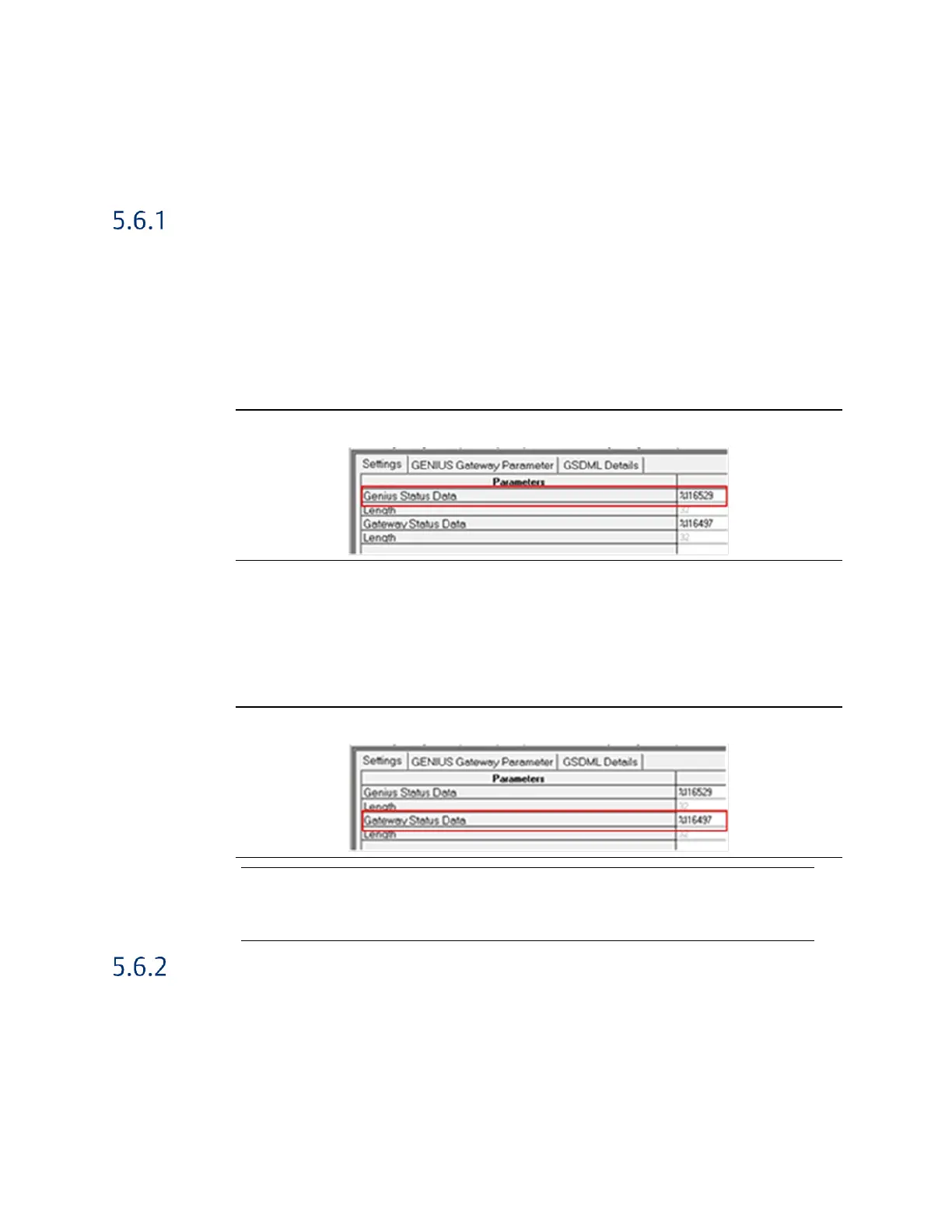
Genius Status Data The GCG provides 32 bits that indicate status information on
devices associated with the GCG’s Genius Bus. The bits indicate
the attachment state for a device. Bit 0 corresponds to a device
at Serial Bus Address 0. Bit 31 corresponds to a device at Serial
Bus Address 31. ON=Attached; OFF=Missing. Refer to the
PACSystems RX3i Genius Communications Gateway User
Manual, GFK-2892, Section 5.1.2.
Figure 26: GCG Genius Status Data Reference Assignments
Gateway Status Data The GCG provides 32 bits of status information for the network
(MRP, Port Availability), Genius Device Fault state, and GCG
Module OK. Refer to the PACSystems RX3i Genius
Communications Gateway User Manual, GFK-2892, Section
5.1.1.
Figure 27: GCG Gateway Status Data Reference Assignments
Note: The reference addresses in the Primary group and the Secondary group must be configured
identically. For example, in Figure 26, the Genius Status Data reference for Primary PLC, Dual
Bus 0, Genius Bus A is %I16529. The Secondary PLC, Dual Bus 0, Genius Bus A is also
configured for %I16529. Similarly, for the Gateway Status Data (Figure 27).
GENIUS Gateway Parameter Tab
Baudrate This setting must be configured to match the current Genius
bus baud rate characteristic.
Output at Startup This parameter must be set to enabled.

 Loading...


