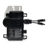
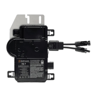
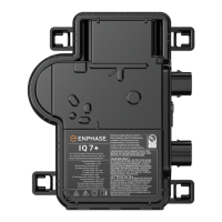
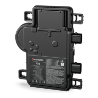
IQ 7 / IQ 7+ / IQ 7X / IQ 7A Installation and Operation
© 2020 Enphase Energy Inc. All rights reserved. 141-00044-02
Step 1: Position the Enphase Q Cable
A. Plan each cable segment to allow drop connectors on the Enphase Q Cable to align with
each PV module. Allow extra length for slack, cable turns, and any obstructions.
B. Mark the approximate centers of each PV module on the PV racking.
C. Lay out the cabling along the installed racking for the AC branch circuit.
D. Cut each segment of cable to meet your planned needs.
WARNING: When transitioning between rows, secure the cable to the rail to prevent cable
damage or connector damage. Do not count on connector to withstand tension.
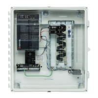
Step 2: Position the Junction Box
A. Verify that AC voltage at the site is within range.
B. Install a junction box at a suitable location on the racking.
C. Provide an AC connection from the junction box back to the electricity network using
equipment and practices as required by local jurisdictions.
 Loading...
