IQ 7 / IQ 7+ / IQ 7X / IQ 7A Installation and Operation
© 2020 Enphase Energy Inc. All rights reserved. 141-00044-02
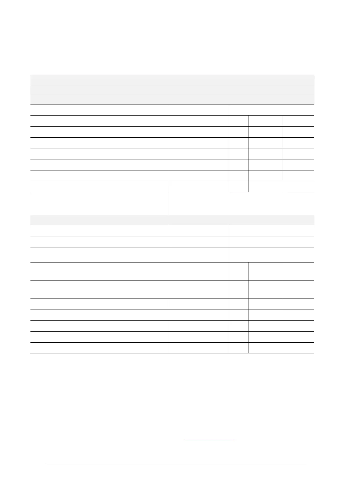
Specifications
The following tables list specifications for the various IQ 7 Series models and for the Q Cable.
IQ7-60-2-INT Microinverter Specifications
Enphase IQ7-60-2-INT Microinverter Parameters
Commonly used module pairings1
Peak power tracking voltage
Minimum / maximum start voltage
Maximum DC input short circuit current (module Isc)
Overvoltage class DC port
DC Port backfeed under single fault
1x1 ungrounded array; No additional DC side protection
required; AC side protection requires max 20A per branch
circuit
Maximum continuous AC output power (-40C to +65C)
Power factor (adjustable)
Nominal AC output voltage range2
230 VAC (single phase)
Nominal output current
230 VAC (single phase)
Overvoltage class AC port
AC port backfeed under single fault
No enforced DC/AC ratio. See the compatibility calculator at module-compatibility.
Nominal Voltage Range can be extended if required by the utility.
 Loading...


