EVCO S.p.A. EV3 CHIL & EVD CHIL | Installer manual ver. 1.2 | Code 1443DCHILE124
page 7 of 46
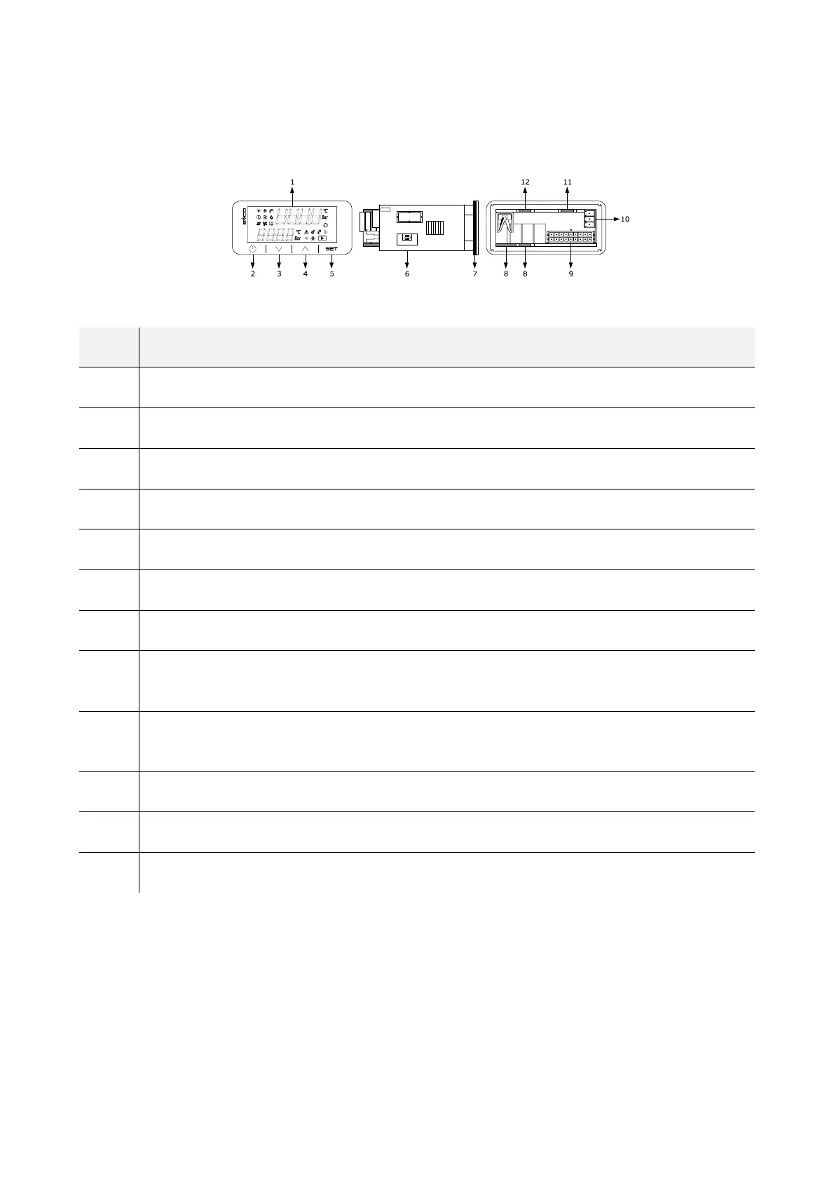
2 DESCRIPTION
2.1 Description of EV3 CHIL
The picture below shows the layout of the EV3 CHIL.
The table below describes each part of the EV3 CHIL.
PART DESCRIPTION
1 Double row LED display, with decimal point and function icons
2 On/Off key, subsequently also called the On/Stand-by key
3 Decrease key, subsequently also called the Down key
4 Increase key, subsequently also called the Up key
5 Setting key, subsequently also called the Set key
6 Micro-switch for the termination of the RS-485 MODBUS line
7 Seal
8
Edge connector joint for the digital output cabling with electro-mechanical relay (for future reference, the digital outputs
DO1... DO4)
9
Male Micro-Fit connector for cabling for the power supply, analogue inputs, digital inputs, analogue outputs and the
INTRABUS powered port
10 If fitted, plug-in screw terminal block for the RS-485 MODBUS port cabling
11 If fitted, the joint of the Edge connector for the triac digital output cabling (for future reference, the digital output TK1).
12 If fitted, the joint of the Edge connector for the triac digital output cabling (for future reference, the digital output TK2)
For more information see subsequent sections.

 Loading...