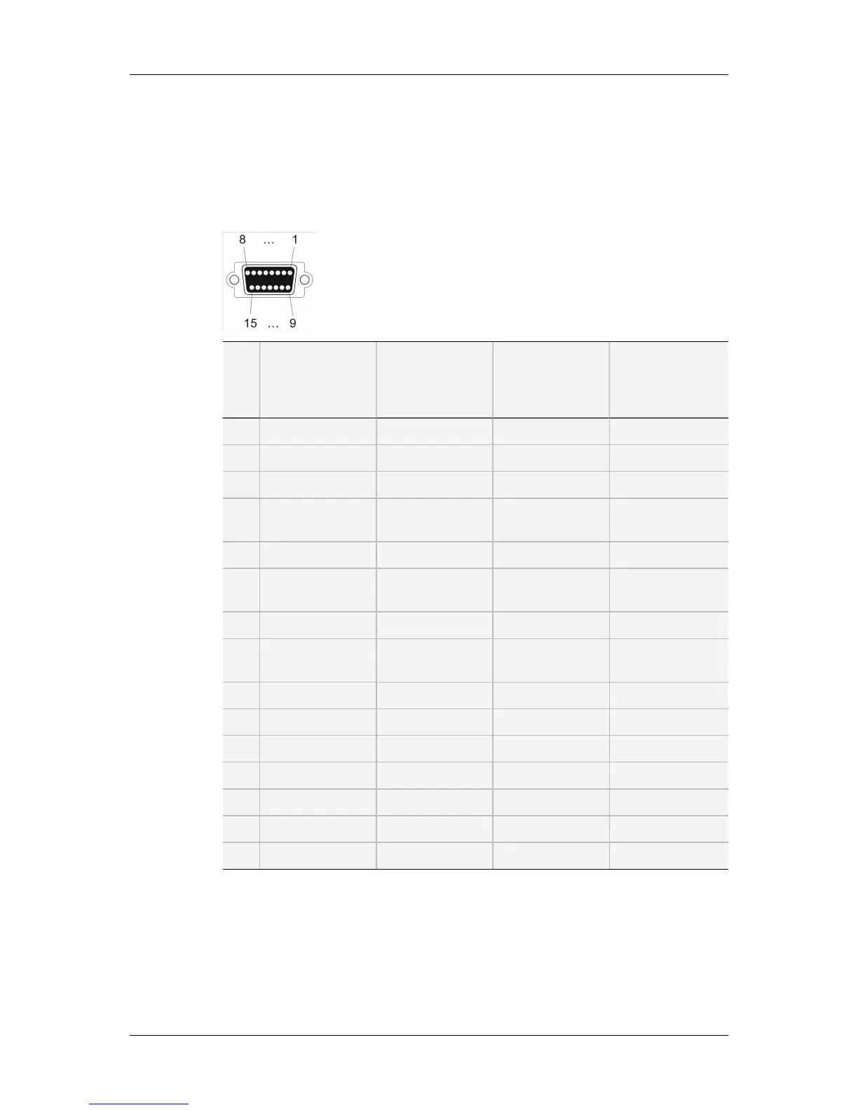
5.4.2. Digital Audio DA-15 Pinout
The digital audio DA-15 connector is illustrated hereunder (connector installed on the rear
panel and viewed from outside). Its pinout is described in the following table where each
column corresponds to one of the 4 available connectors.
Pin
#
DA-15 connector
#1
Inputs 1-8
(mono)
DA-15 connector
#2
Inputs 9-16
(mono)
DA-15 connector
#3
Outputs 1-8
(mono)
DA-15 connector
#4
Outputs 9-16
(mono)
1 Gnd Gnd Gnd Gnd
2 AES input 1/2 + AES input 9/10 + AES output 1/2 + AES output 9/10 +
3 Gnd Gnd Gnd Gnd
4 AES input 3/4 + AES input 11/12 + AES output 3/4 + AES output 11/12
+
5 Gnd Gnd Gnd Gnd
6 AES input 5/6 + AES input 13/14 + AES output 5/6 + AES output 13/14
+
7 Gnd Gnd Gnd Gnd
8 AES input 7/8 + AES input 15/16 + AES output 7/8 + AES output 15/16
+
9 AES input 1/2 - AES input 9/10 - AES output 1/2 - AES output 9/10 -
10 Gnd Gnd Gnd Gnd
11 AES input 3/4 - AES input 11/12 - AES output 3/4 - AES output 11/12 -
12 Gnd Gnd Gnd Gnd
13 AES input 5/6 - AES input 13/14 - AES output 5/6 - AES output 13/14 -
14 Gnd Gnd Gnd Gnd
15 AES input 7/8 - AES input 15/16 - AES output 7/8 - AES output 15/16 -
64 5. Hardware Installation and Cabling
EVS Broadcast Equipment SA Issue 12.05.C- November 2014
 Loading...


![Preview: EVS XT[2]](https://data.easymanua.ls/products/617905/200x200/evs-xt-2.webp)


