V3X COD Modules LEDs
The following table lists the LEDs available on then V3X COD modules (from left to right):
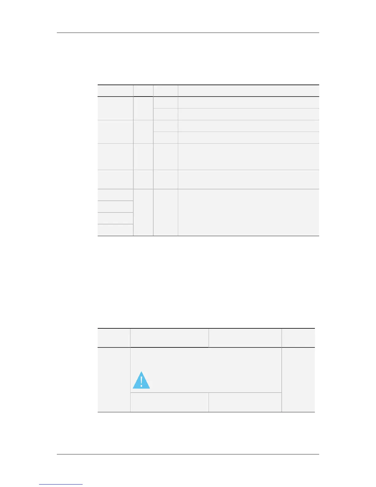
LED Color Status Function
CPU Green Blinking Indicates CPU activity.
On There is a problem with the module processor.
PLAY Green On The module is set in play mode by the software.
Off The module is set in record mode.
PVID Green On A valid video signal has been detected on the J8
connector (SD/HD SDI input), whether the module is in
play or record mode.
TF
(transfer)
Green Blinking Data transfers occur between the module and the H3X
board.
M1 — — Not used.
M2
M3
M4
6.2.2. CODConnectivity in SD and HD
Connector Assignments
This section describes the connector assignments and layout for the video standards SD
525i, SD 625i, HD 1080i and HD 720p.
The specific connectivity for HD 3D/1080p Dual Link and 3D/1080p Single Link 3Gbps is
described in the following sections.
Connector SD mode HD mode
Connector
label
J1 J5 is factory-wired to the backplane instead of J1. You can
connect J1 instead of J5 if CVBS monitoring is required in
SD or HD mode.
SDI monitoring is no longer available on J1.
CHAR SD
CVBS monitoring output (SD) CVBS monitoring output
(SD, down-converted)
88 6. Boards Description
EVS Broadcast Equipment SA Issue 12.05.C- November 2014
 Loading...


![Preview: EVS XT[2]](https://data.easymanua.ls/products/617905/200x200/evs-xt-2.webp)


