45°
<
45°
<
21
ASSEMBLY AND INSTALLATION INSTRUCTIONS
Chapter5
CONNECTION TO THE SMOKE EVACUATION SYSTEM
SMOKE CHANNEL OR CONNECTIONS
To mount the smoke channels, non- ammable elements will have to be used, ideal for resisting fuel products
and their eventual condensing.
The use of exible metal and asbestos cement pipes to connect the appliances to the ue is forbidden, even for
pre-existing smoke channels.
There must be continuity between the smoke channel and the ue so that the ue does not lean on the
generator. The smoke channels must not cross rooms where the installation of the combustion appliances is
not allowed.
The mounting of the smoke channels must be carried out in order to guarantee smoke seal for the appliance
functioning conditions, limit the forming of condensate and avoid it being transported towards the appliance.
The mounting of horizontal routes must be avoided.
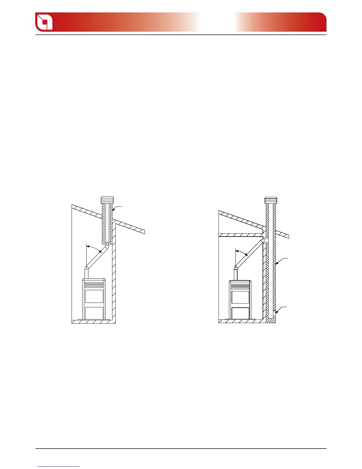
For appliances where ceiling or wall non coaxial discharges respect to the appliance smoke outlet have to be
reached, the direction changes will have to realised using open elbows not higher than 45° (see gures below).
Insulating
product
Flue
Inspection
For the heat generator appliances equipped with electric fan for expelling fumes, the instructions below
must be followed:
The horizontal routes will have to have a minimum upward slope of 3%
The length of the horizontal route must be minimal and, however, not higher than 3 meters
The number of direction changes including the one for e ect of using the “T” element must not be
more than 4 (if 4 bends are used, use double wall piping with an internal diameter of 120 mm.)
In any case, the smoke channels must seal the fuel and condensing products and be insulated if they pass
externally to the installation room.
The use of counterslope elements is forbidden.
The smoke channel must allow the recovery of soot or be brushed.
The smoke channel must be at constant section. Any section changes are only allowed at the ue
coupling.
gure 5.1 gure 5.2
 Loading...