Drives
3.
180
Ref.1912
DDS
HARDWARE
· 134 ·
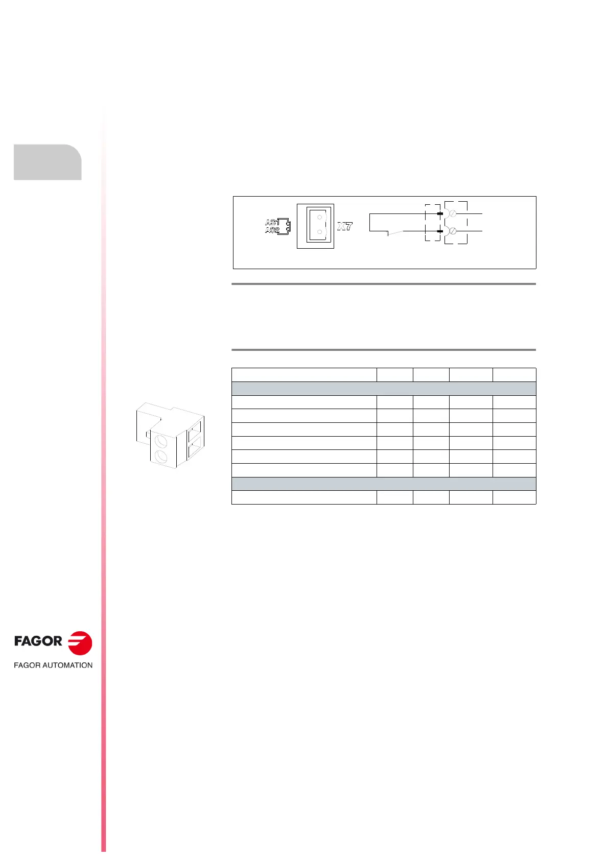
X7 connector
X7. Status of the safety relay
This connector X7 of the modular drive is associated with the second contact
(N.C., Normally Closed) of an internal safety relay (with guided contacts).
The status of the relay (initially closed) may be acknowledged through the
two pins and a CNC, PLC or control panel, i.e. that the integrated safety
relay has actually opened or closed. These two terminals are identified at
the drive as AS1-AS2. The opening or closing of this relay depends on
whether 24 V DC are present or not at pin 2 «Drive Enable» of control
connector X2. For further detail on this connector, see section 9.2. Drive
Enable input and AS1-AS2 feedback output of chapter 9. FUNCTIONAL
SAFETY in this manual.
The following table shows the values for gap, tightening torque, sections
and other data of aerial plug-in connector X7:
F. H3/74
X7 connector. External acknowledgment of the status of the integrated
safety relay.
T. H3/12 Pins of aerial plug-in connector X7. Technical data.
AXD|SPD|MMC 1.XX 2.XX 3.XX
Connector data
Nr of poles 2 2 2
Gap (mm) 5 5 5
Min./max. tightening torque (N·m) 0.5/0.6 0.5/0.6 0.5/0.6
Screw thread M3 M3 M3
Min./max. section (mm²) 0.2/2.5 0.2/2.5 0.2/2.5
Rated current In (A) 12 12 12
Connection data
Length to strip (mm) 7 7 7
1
2
AS1
AS2
INTERNAL
RELAY CONTACT
 Loading...