Installation
8.
310
· 274 ·
Ref.1912
DDS
HARDWARE
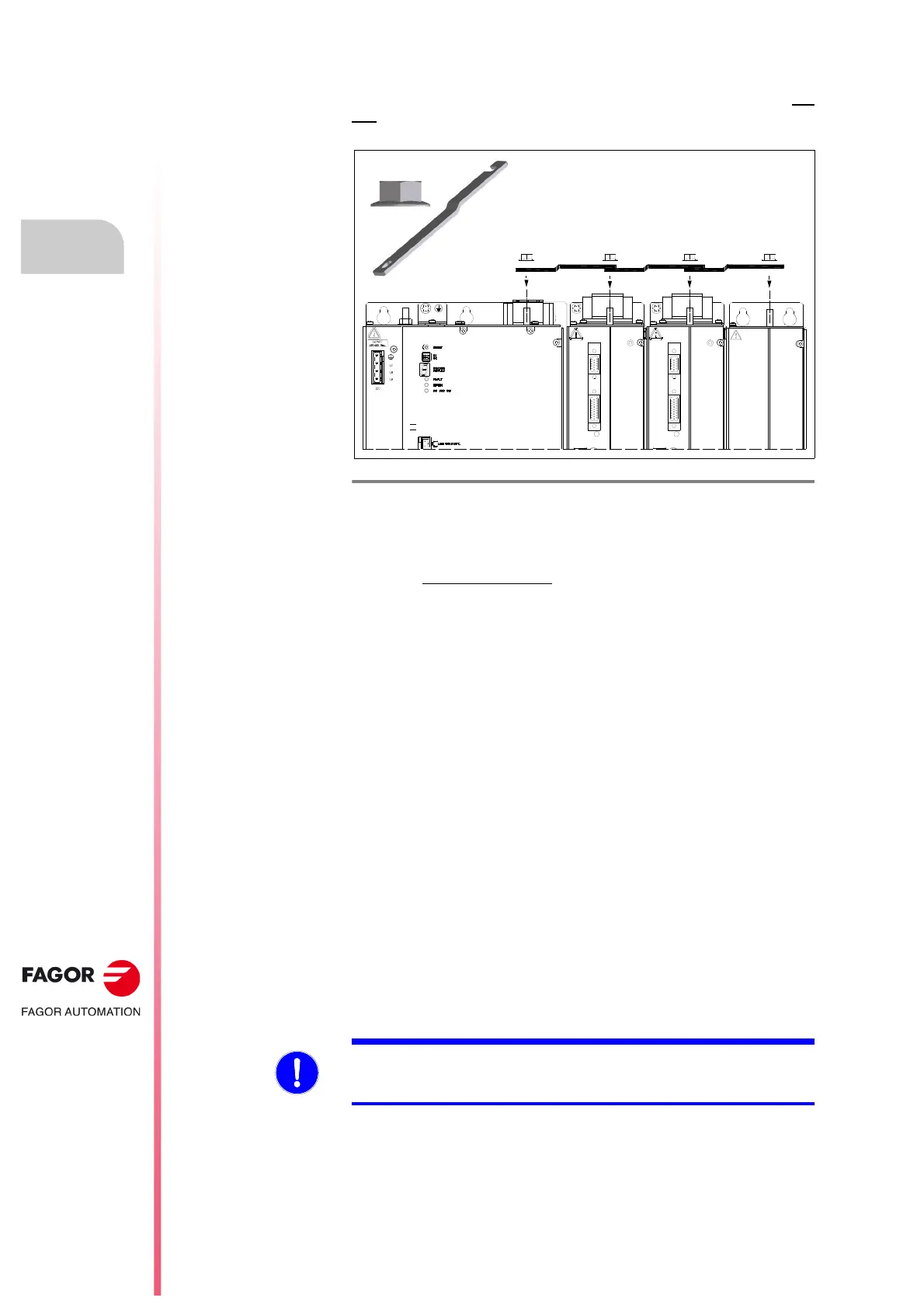
Joining the chassis between modules
The chassis of the modules must be connected to each other through the M6
bolt on top of each module. To do this, the irregular plate and the nut
supplied as accessories with each module must be used.
The tightening torque must be between 2.3
2.8 N·m.
Connecting these terminals by means of metal plates offers mechanical
rigidity; but it does not guarantee
proper ground connection of each module.
To replace a module in case of a failure or remove it from the DDS system
for inspection, follow these steps to “free” it from the other modules.
A. Loosen the screw and the nut of the affected module.
B. Loosen the nut of the adjacent module on each side that joins it to the
affected module.
C. Rotate the plate of the affected module and that of the one to its left, see
figure
F. H8/9 .
After these steps, the drive will be totally free from the rest of the modules
that were joined by the plate.
All the cables connecting it to the rest of the modules must also be removed.
Ground connection
The chassis of each modules must be connected to a single point and from
there to the ground terminal of the electrical cabinet. When applying a 10 A
current between this ground point and any of these points, the voltage drop
must not exceed 1 V. Use the nuts supplied with each module to make the
ground connection.
F. H8/9
Joining the chassis between modules. Include the BPM module only if
applicable.
RPS 45
X4
X3
UVW
DRIVE MODULE
X5
X6
X4
X3
UVW
DRIVE MODULE
X5
X6
OTECTION MODULE
MANDATORY. It is up to the system integrator to meet all the requirements
of local and national electrical codes as well as all the regulations applicable
regarding the grounding of the whole unit.
 Loading...