 Loading...
Do you have a question about the Fagor DDS XPS-25 and is the answer not in the manual?
Schematic representation of the elements composing the DDS system.
Steps for configuring and installing the DDS system.
Conditions related to the operating environment for the DDS system.
Electrical specifications and requirements for the DDS system.
Details on PS-25B4 and PS-65A non-regenerative power supplies.
Details on XPS-25 and XPS-65 regenerative power supplies.
Details on RPS power supplies in RPS and RB6 modes.
Overview and models of AXD, SPD, and MMC modular drives.
Overview and models of ACD, SCD, and CMC compact drives.
Description and technical data for FAGOR MAIN FILTER models.
Details on XPS and RPS chokes for regenerative power supplies.
Information on external ballast resistors with internal or external thermostats.
Details on the CM-1.75 capacitor module for DC BUS energy storage.
Details on the APS-24 auxiliary power supply module.
Description and technical data for the BPM bus protection module.
Guide for selecting synchronous motors and associated drives based on torque and speed.
Procedure for selecting asynchronous spindle motors and drives for machine tools.
Criteria for selecting the appropriate power supply based on motor requirements.
Guidance on selecting the CM-1.75 capacitor module for DC BUS applications.
Guidelines for selecting the correct ballast resistor for power supplies and drives.
Connecting the DDS system to the three-phase mains, including required protection devices.
Selection and installation of fuses for DDS system protection.
Requirement and selection of differential breakers for DDS systems.
Use of transformers for voltage adaptation and isolation in DDS systems.
Mandatory installation of mains filters for EMC compliance.
Function and selection of line inductance (chokes) for harmonic reduction.
Types of distribution diagrams (TN, TT, IT) and their impact on cabling.
Information on FAGOR mains connection cables for power supply and compact drives.
Details on FAGOR mains connection cables for power supplies and compact drives.
Information on FAGOR power cables for connecting motors and drives.
Range of motor encoder cables for FXM, FKM, and FM7 motors.
Adapter cable for transmitting absolute signals from linear/torque motors to AXD/ACD drives.
Cables for connecting incremental or absolute feedback devices.
Cables for encoder simulation and control signals.
Fiber optic cables for SERCOS-II communications between CNC and drives.
FAGOR supplied CAN cables for communication between drives and master devices.
Adapter for connecting RS-232 or RS-422 serial lines with VT panels.
Connection diagrams for RS-232 serial lines between PC, VT, and drives.
Connection diagrams for RS-422 serial lines between VT and drives.
Considerations for placing the DDS system within an electrical cabinet.
Temperature limits for the electrical cabinet housing the DDS system.
Guidelines for electrical installation, EMC, and wiring practices.
Recommendations for equipotential wiring and cable shielding.
Strategies for cooling electrical cabinets containing the DDS system.
Precautions for connecting inductive components like contactors and relays.
Procedure for installing the DDS system modules in the electrical cabinet.
Instructions for connecting modules via the power bus and chassis.
Procedure for mechanically connecting module chassis using bolts and plates.
Requirements for grounding the DDS system chassis and cable shields.
Connecting modules using the internal bus via ribbon cables.
Configuration for connecting internal or external ballast resistors.
Procedure for connecting and disconnecting ballast connectors on compact drives.
Installation guide for external ballast resistors with internal thermostat.
Installation guide for external ballast resistors with external thermostat.
Installation guide for external ballast resistors with internal thermostat and fan.
Procedure for installing two external ballast resistors in parallel.
Information on Ohm values for external ballast resistors.
Connecting ballast resistors to the BPM module.
Procedure for installing ER+TH-18/1100 resistor to the BPM module.
Procedure for installing two ER+TH-18/1100 resistors in parallel to BPM.
Procedure for installing three ER+TH-18/1100 resistors in parallel to BPM.
Considerations for heat dissipation from external ballast resistors.
Connecting power supplies to modules and drives.
Details on the 24 V DC supply for control circuits of modules.
Connecting the APS-24 to PS-65A and modular drives.
Connecting auxiliary power supply to PS-25B4 and XPS.
Connecting auxiliary power supply to RPS power supplies.
Connecting motor feedback and control signals.
Connecting the motor feedback device (encoder) to the drive.
Using the TSIA-1 adapter for galvanic isolation of temperature sensors.
Connecting linear or rotary encoders for direct feedback.
Connecting the encoder simulator board to the CNC.
Receiving analog velocity commands from the CNC via connector X7.
Protection circuits for optocouplers when connecting inductive loads.
Connecting drives to CNC via SERCOS digital communication.
Connecting drives in the SERCOS ring and closing the ring.
Proper handling procedures for fiber optic cables.
Selecting SERCOS transmission speed using the BOOT button.
Procedure for changing the SERCOS transmission speed.
Possible values for SERCOS transmission speed.
Connecting the ESA Video Terminal to FAGOR drives via CAN bus.
Connecting FAGOR 8037 CNC to drives via CAN bus.
Connecting FAGOR 8055i CNC to drives via CAN bus.
Overview of CAN bus functions and connection.
Ensuring RT activation for external elements connected to the CAN bus.
Selecting CAN transmission speed using the BOOT button.
Procedure for changing CAN transmission speed.
Possible values for CAN transmission speed.
Connecting the ESA Video Terminal to FAGOR drives via CAN bus.
Connecting FAGOR 8037 CNC to drives via CAN connector.
Connecting FAGOR 8055i CNC to drives via CAN connector.
Connecting FAGOR UC 8055 to drives via CAN connector.
Connecting drives via RS-232/422 serial line without adapter.
RS-422 serial line connection between ESA VT and MMC/CMC drives without adapter.
RS-422 serial line connection between ESA VT and MMC/CMC drives without adapter.
Connecting PC/ESA VT via RS-232/422 serial line for project transfer.
Connecting PC to drive via RS-232 serial line for setup.
Final checks after installation to ensure proper setup.
List of checks for mechanical and electrical installation.
Topics covered in the functional safety chapter.
Information on TÜV SÜD functional safety standards.
Requirements for EC marking of machines using drive safety functions.
Overview of safety functions like STO, Cat. 3 PL d - SIL 2.
Interface for STO safety function: Drive Enable input and AS1-AS2 feedback.
How the system detects and reacts to faults in safety functions.
Design requirements for safety functions, including STO and SS1.
Safety precautions for electrical installation and operation.
Assessment and reduction of residual risks associated with safety functions.
Technical data for calculating Performance Level (PL) and Safety Integrity Level (SIL).
Response times for machine and drive safety functions.
Recommendations for cabling and grounding safety functions.
Procedures for acceptance and partial acceptance tests of safety functions.
Guidelines for mission times, failure probabilities, and maintenance.
Requirements for decommissioning and disposal of the unit.
Overview of safety, environmental, and EMC considerations.
Connection diagram for SPD modular drive with FM7 motor and TTL encoder.
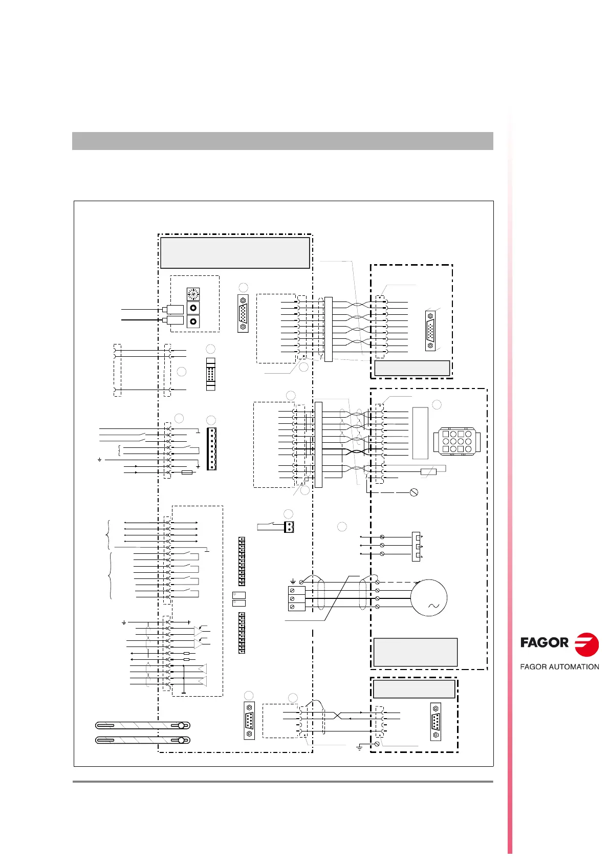
Connection diagram for AXD drive with FKM servomotor and E3 encoder.
Connection diagram for AXD drive with FXM servomotor and E1 encoder.
Connection diagram for SCD compact drive with FM7 motor and TTL encoder.
Connection diagram for ACD drive with FKM servomotor and encoder.
Connection diagram for ACD drive with FXM servomotor and encoder.
Connection diagram for ACD 1.25 drive with linear motor and S2AI encoder.
General diagrams for power and control circuits in the electrical cabinet.
Connection diagrams for a DDS system with PS-65A power supply.
Connection diagrams for a DDS system with PS-25B4 power supply.
Connection diagrams for a DDS system with XPS power supply.
Connection diagrams for a DDS system with RPS power supply.
Connection diagrams for ACD/SCD compact systems using SERCOS.
Connection diagrams for ACD/SCD compact systems using CAN bus.
Connection diagrams for mixed AXD/SCD systems using SERCOS.
Connection diagrams for mixed AXD/SCD systems using CAN bus.
Diagrams for connecting holding brakes to FXM and FKM motors.
Diagram for start/delta connection switching on FM7 spindles.
Dimensions for PS-25B4 power supply module.
Dimensions for PS-65A non-regenerative power supply.
Dimensions for XPS-25 regenerative power supply.
Dimensions for XPS-65 regenerative power supply.
Dimensions for RPS-20 regenerative regulated power supply.
Dimensions for RPS-45 regenerative regulated power supply.
Dimensions for RPS-75 regenerative regulated power supply.
Dimensions for RPS-80 regenerative regulated power supply.
Dimensions for APS-24 auxiliary power supply.
Dimensions for AXD/SPD/MMC 1.08 and 1.15 modular drives.
Dimensions for AXD/SPD/MMC 1.25 modular drives.
Dimensions for AXD/SPD/MMC 1.35 modular drives.
Dimensions for AXD/SPD/MMC 2.50/2.75 and SPD 2.85 drives.
Dimensions for AXD/SPD/MMC 3.100/3.150 modular drives.
Dimensions for AXD/SPD/MMC 3.200/3.250 modular drives.
Dimensions for ACD/SCD/CMC 1.08 and 1.15 compact drives.
Dimensions for ACD/SCD/CMC 1.25 compact drives.
Dimensions for ACD/SCD/CMC 2.35/2.50 and 2.75 compact drives.
Dimensions for the BPM bus protection module.
Dimensions for the CM-1.75 capacitor module.
Dimensions for FAGOR MAIN FILTER models.
Dimensions for XPS-25 and XPS-65A chokes.
Dimensions for RPS-20, RPS-45, and RPS-75-3 chokes.
Dimensions for external ballast resistors with external thermostat.
Dimensions for external ballast resistors with internal thermostat.
Dimensions for external ballast resistors with thermostat and fan.
Dimensions for external thermostat.
Denominations for FAGOR FXM and FKM synchronous servo motors.
Denominations for FAGOR FM7 and FM9 asynchronous motors.
Denominations for AXD, SPD, and MMC modular drives.
Denominations for ACD, SCD, and CMC compact drives.
Denominations for MMC and CMC positioning drives.
Denominations for FAGOR PS, XPS, and RPS power supplies.
Denominations for FAGOR auxiliary modules like filters, chokes, etc.
Denominations for FAGOR power, signal, and interface cables.
Denominations for connectors on FXM and FKM servo motors.
Example of how to place an order for FAGOR catalog products.
Information on identifying electronic units via characteristic plates.
Line voltage ranges supported by FAGOR drives and power supplies.
Compatibility of elements with mains voltages and drive versions.
Guidelines for replacing 380 V AC modules with 460 V AC modules.
Compatibility of VECON boards with software versions.
Information on VECON-2 board replacement and software versions.
Information on VECON-3 board replacement and software versions.
Information on VECON-4 board replacement and software versions.
Loading software versions on VECON-2 boards.
Loading software versions on VECON-3 boards.
Loading software versions on VECON-4 boards.
Compatibility of SERCOS card with software versions and transmission speeds.
Compatibility of CAN board with FAGOR drives and software versions.
Compatibility of CAPMOTOR-x boards with feedback types and software versions.
Compatibility of VECON-x boards with software versions.