15
• Operator moves ground speed control levers out of their
neutral positions before disengaging parking brake.
Test 4 - Blade Brake Check
Mower blades and mower drive belt should come to a
complete stop within seven (7) seconds after electric PTO
switch is turned off (or operator rises off seat). If mower drive
belt does not stop within seven (7) seconds, see your dealer.
NOTE: Once the engine has stopped, PTO switch must be
turned off, parking brake must be engaged, and the ground
speed control levers must be locked in the NEUTRAL position
after the operator returns to the seat in order to start the
engine.
WARNING
If the unit does not pass a safety test, do not operate it. See
your authorized dealer. Under no circumstance should you
attempt to defeat the purpose of safety interlock system.
Features and Controls
Control Functions and Locations
The information below briefly describes the function of
individual controls. Starting, stopping, driving, and mowing
require the combined use of several controls applied in
specific sequences. To learn what combination and sequence
of controls to use for various tasks see the Operation section.
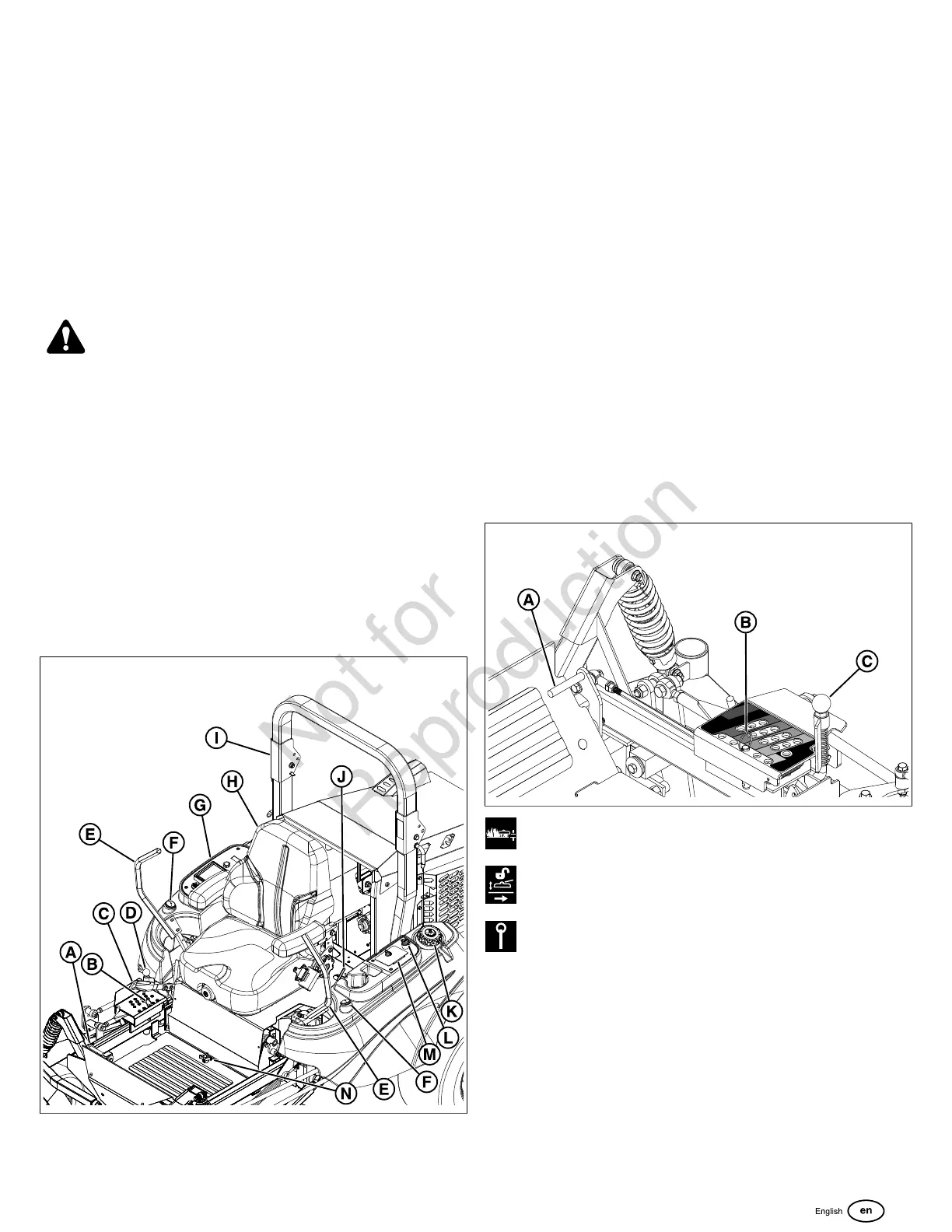
Zero-Turn Rider Controls
6
A. Deck Lift Pedal
B. Cutting Height Adjustment Pin
C. Parking Brake
D. Deck Lift Lock Lever and Lockout Plate
E. Ground Speed Control Levers
F. Fuel Level Gauge
G. Instrument Control Panel
H. Seat
I. Roll Bar
J. Seat Latch
K. Fuel Tank Cap
L. Power Outlet
M. Storage Compartment
N. Removable Floor Plate
O. Transmission Oil Fill/Tank
P. Hydraulic Release Valves (One per pump)
Deck Lift Pedal, Cutting Height Adjustment Pin, and
Deck Lift Lock Lever: Press the deck lift pedal (A, Figure 7)
forward to raise the mower deck until it locks into the 6" (15,2
cm) position. Place the cutting height adjustment pin (B) in
the desired cutting height hole and release the deck lift lock
lever (C).
7
Cutting Height Adjustment Pin
Deck Lift Lock Lever
Cutting Height Pin Storage Hole
Deck Lift Lockout Plate:
The deck lift lock lever lockout plate (A, Figure 8) can be
used to prevent the mower deck from locking the deck in the
6" (15,2 cm) position if you raise the deck during operation to
clear an object.
 Loading...