48 ferrismowers.com
16. Run the mower under no-load condition for about five (5)
minutes to break in the new belts.
PTO Clutch Drive Belt Replacement
1. Park the unit on a flat, level surface such as a concrete
floor. Disengage the PTO, engage the parking brake, turn
the ignition switch to OFF, and remove the ignition key.
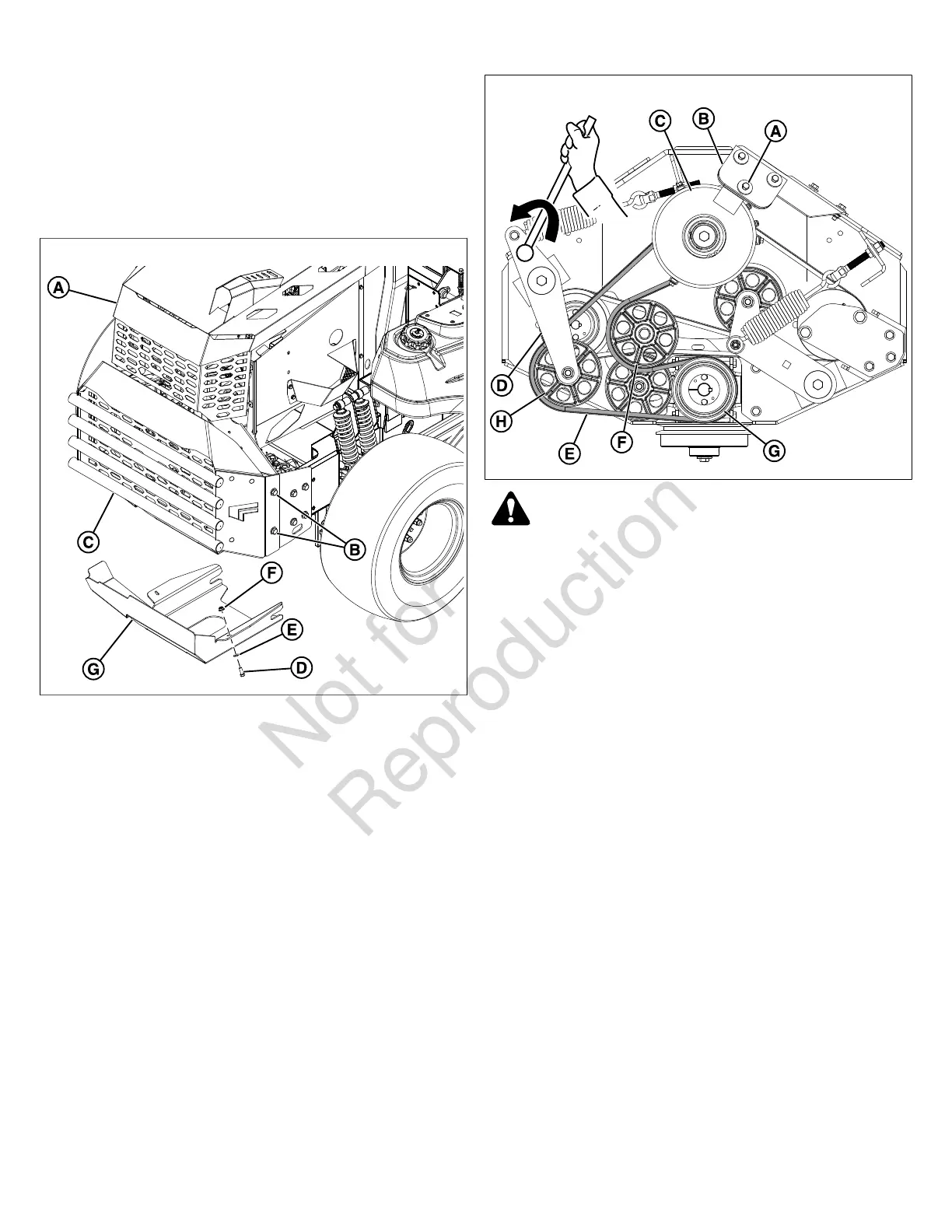
2. Release the hood latch and raise the hood (A, Figure 78).
78
3. Remove the four (4) 1/2 bolts, washers, and nuts (B) that
secure the rear bumper assembly (C) to the unit.
4. Remove the rear bumper assembly from the unit.
5. Remove the two (2) 3/8 bolts (D), washers (E), and nuts
(F) that secure the skid plate (G) to the unit.
6. Remove the skid plate from the unit.
7. Remove the hardware (A, Figure 79) that fastens the
clutch anchor pad (B) to the clutch (C). Disconnect the
wire harness from the PTO clutch.
79
WARNING
Use extreme caution when rotating the idler arm with
the breaker bar, due to the increased tension in the
spring as the idler arm is being rotated. Injury may
result if the breaker bar is prematurely released while
the spring is under tension.
8. Using a 1/2" breaker bar, place the square end in the
square hole located in the idler arm (D). Carefully rotate
the idler arm counter-clockwise which will relieve the
tension on the belt (E) exerted from the idler arm.
9. Remove the belt from the stationary idler pulley (F) and
the gearbox pulley (G).
10. Carefully release the tension on the breaker bar until the
idler arm stops movement.
11. Remove the belt from the adjustable idler pulley (H) and
the PTO clutch pulley.
12. Install the new belt on the PTO clutch pulley and the
adjustable idler pulley making sure that the V-side of the
belt runs in the grooves of the pulley.
13. Carefully rotate the idler arm with the breaker bar
counter-clockwise and install the V-side of the belt in
the grooves of the gearbox pulley and the backside of the
belt against the face of the stationary idler pulley.
14. Carefully release the tension on the breaker bar.
15. Install the clutch anchor pad to the clutch with the
hardware previously removed. Connect the wire harness
to the PTO clutch and make sure that the wires are clear
of any moving parts.
16. Measure the coil-to-coil length (A, Figure 80) of the belt
tensioning spring (B). The measurement should equal
8-1/4" (20,9 cm). If not, adjust the spring length.
 Loading...