50 ferrismowers.com
Note:The spacers shims are added as needed for proper
alignment during manufacturing. Figure 82 depicts three (3)
shimsbut your unit might have a different number of shims.
11. Remove the belt from the unit.
12. Install the belt onto the pump drive pulley (I, Figure 81),
the right hand pump pulley (J), and the adjustable idler
pulley (K). Make sure that the V-side of the belt aligns
with the grooves of the pump drive pulley and the right
hand pump pulley and that the back side of the belt
contacts the face of the adjustable idler pulley.
13. Align the pump support bearing (B, Figure 82) with the
shaft (H) on the right hand pump pulley.
14. Secure the pump support bearing to the unit using the
three (3) 3/8" bolts (C), washers (D), and nuts (E) that
were previously removed.
15. Verify that the pump support bearing is properly aligned
onto the shaft on the right hand pump pulley and then
tighten the two (2) set screws (A).
16. Using a 1/2" breaker bar, place the square end in the
opening located in the idler arm (A, Figure 81). Carefully
rotate the breaker bar counter-clockwise.
17. Install the belt onto the left hand pump pulley (C) and the
stationary idler pulley (L). Make sure the the V-side of the
belt aligns with the grooves of the left hand pump pulley
and that the backside of the belt contacts the face of the
stationary idler pulley.
18. Carefully release the tension on the breaker bar.
19. Tighten the hardware (D) that secures the PTO clutch belt
idler arm (E).
20. Tightenthe hardware (F) that secures the stationary idler
pulley (G).
21. Tighten the hardware (H) that secures the pump drive belt
idler arm (A).
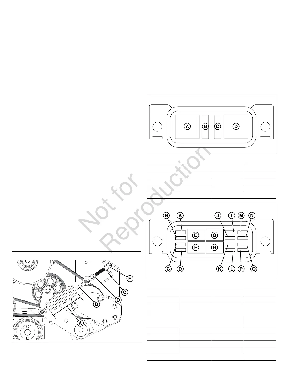
22. Measure the coil-to-coil length (A, Figure 83) of the belt
tensioning spring (B). The measurement should equal
8" (20,3 cm). If not, adjust the belt spring length.
83
23. Loosen the jam nut (C) on the spring anchor (D).
24. Turn the adjustment nut (E) until the measurement of
8" (20,3 cm) is achieved.
25. Install the PTO clutch drive belt. See PTO Clutch Drive
Belt Replacement for installation instructions.
Fuse Location and Identification
The electrical system for this unit is equipped with two (2)
fuse boxes that contain several fuses and relays. The fuse
boxes can be accessed by releasing the seat latch and
raising the seat plate. The fuse boxes are located on the
frame rail in front of the radiator screen. See the charts and
figuresbelow for the circuit and amperage of the fuses.
84
Fuse Block One (Figure 84)
Callout Function Amperage Fuse/Relay
A Start 80 amp Relay
B Start 20 amp Fuse
C Glow Plugs 25 amp Fuse
D Glow Plugs 80 amp Relay
85
Fuse Block Two (Figure 85)
Callout Function Amperage Fuse/Relay
A Spare 5 amp Fuse
B Spare 10 amp Fuse
C Spare 20 amp Fuse
D Fuel Pump Relay
Coil
5 amp Fuse
E Engine 35 amp Relay
F Spare 35 amp Relay
G PTO 35 amp Relay
H Fuel Pump 35 amp Relay
I PTO 20 amp Fuse

 Loading...