9
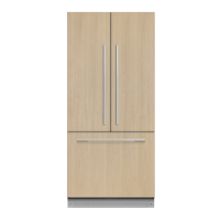
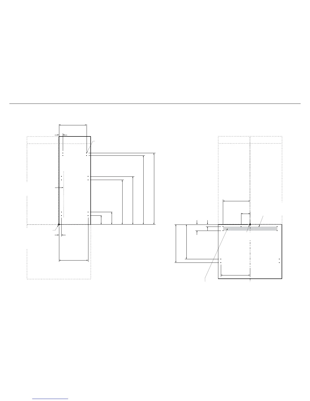
6 CUSTOM DOOR PANEL INSTALLATION DIMENSIONS
All measurements to be made
from inner bottom corner.
For the second panel mirror
and repeat dimensions using
inner bottom corner as the
reference point.
Ensure handle is mounted
29/16” (65mm) from inner edge
of panel to the center – this will
avoid interference with brackets.
13/8” (35mm)
16 11/32” (415mm)
23/16” (56mm)
4 31/32”
(126mm)
6 31/32”
(177mm)
24 31/32” (634mm)
26 31/32” (685mm)
38 21/32” (982mm)
40” (1016mm)
Ø 3/32” (1.25mm) REF
12x Pilot holes recommended for bracket attachment.
(Do not penetrate front surface).
15 15/32” (393mm)
TOP PANEL – REAR VIEW
Ø 3/32” (1.25mm) REF
10x Pilot holes recommended
forbracket attachment.
(Do not penetrate front surface).
153/16” (386mm)
5 3/32”
(129mm)
11/8”
(29mm)
3 15/32”
(88mm)
19 13/32” (493mm)
21 11/32” (542mm)
163/8” (416mm)
All measurements to be made
from top and centerline.
BOTTOM PANEL – REAR VIEW
Cut outs are located in attachment bracket for Fisher & Paykel handles only.
Iflocating custom handle in the shaded area above, ensure handle screw heads
arecounter sunk into back of panel to avoid interference with hanging bracket.
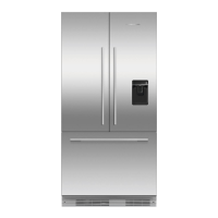
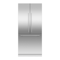
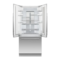
The drawings below apply to non-Water dispensing models only (RS36A72J). Dimensions apply for the preparation and installation of custom door panels.
For Dwg and Dxf files of the below panel preparation download the folder on thekitchentools.fisherpaykel.com.
 Loading...