FLEX-6000 Signature Series – FLEX-6000 Hardware Reference Manual
Page 24 of 48
Copyright 2016 FlexRadio Systems. All Rights Reserved.
7.1.1 Power Pole 30 Amp
The Anderson Power Pole™ connector contains 30 Amp pins to minimize voltage drop
during transmit. The RED connection should be connected to the positive (+) lead of the
power source. The BLACK connection should be connected to the negative (-) lead of the
power source.
I - If you choose to use your own Power Pole cabling, be sure to properly size the wire and
the Power Pole connector to minimize voltage drop during transmit. Excessive voltage
drop can cause lower transmit power output levels.
7.1.2 Fused Internally at 30 Amps
The power input has a protective 30 Amp automotive “blade type” fuse inside the radio
case. Should you ever need to replace the internal fuse, remove the top cover and locate
the fuse in the rear corner of the PA board just inside the case adjacent to the Anderson
Power Pole connector.
! – NEVER USE A FUSE WITH A CURRENT RATING HIGHER THAN 30 AMPS! FAILURE TO
PROPERLY USE THIS SAFETY DEVICE COULD RESULT IN DAMAGE TO YOUR RADIO, POWER
SUPPLY, OR CREATE A FIRE RISK.
7.2 USB 2.0 PORTS
The USB 2.0 ports are used for SmartSDR specific functions only. Do not connect
unqualified USB devices to the FLEX-6000. Refer to the SmartSDR documentation for
information about how these work.
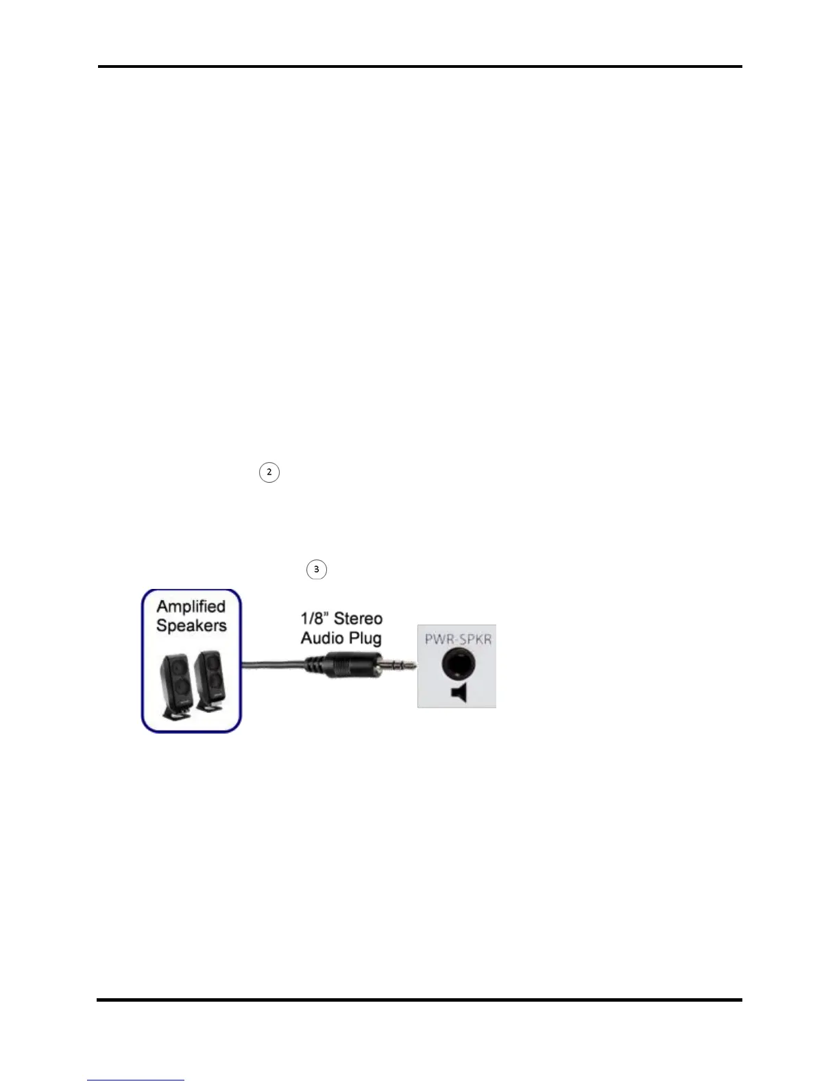
7.3 POWERED SPEAKERS
The powered speaker connector is a 1/8” TRS stereo connector. Stereo powered computer
speakers should be used with this connector. Tip is the left channel, Ring is the right
channel and Sleeve is common. The audio level is a nominal standard consumer (-10 dBV)
line level. Do not use a mono or TS connector that grounds the “ring” portion of the
connector.
 Loading...