System parts
10
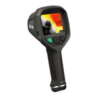
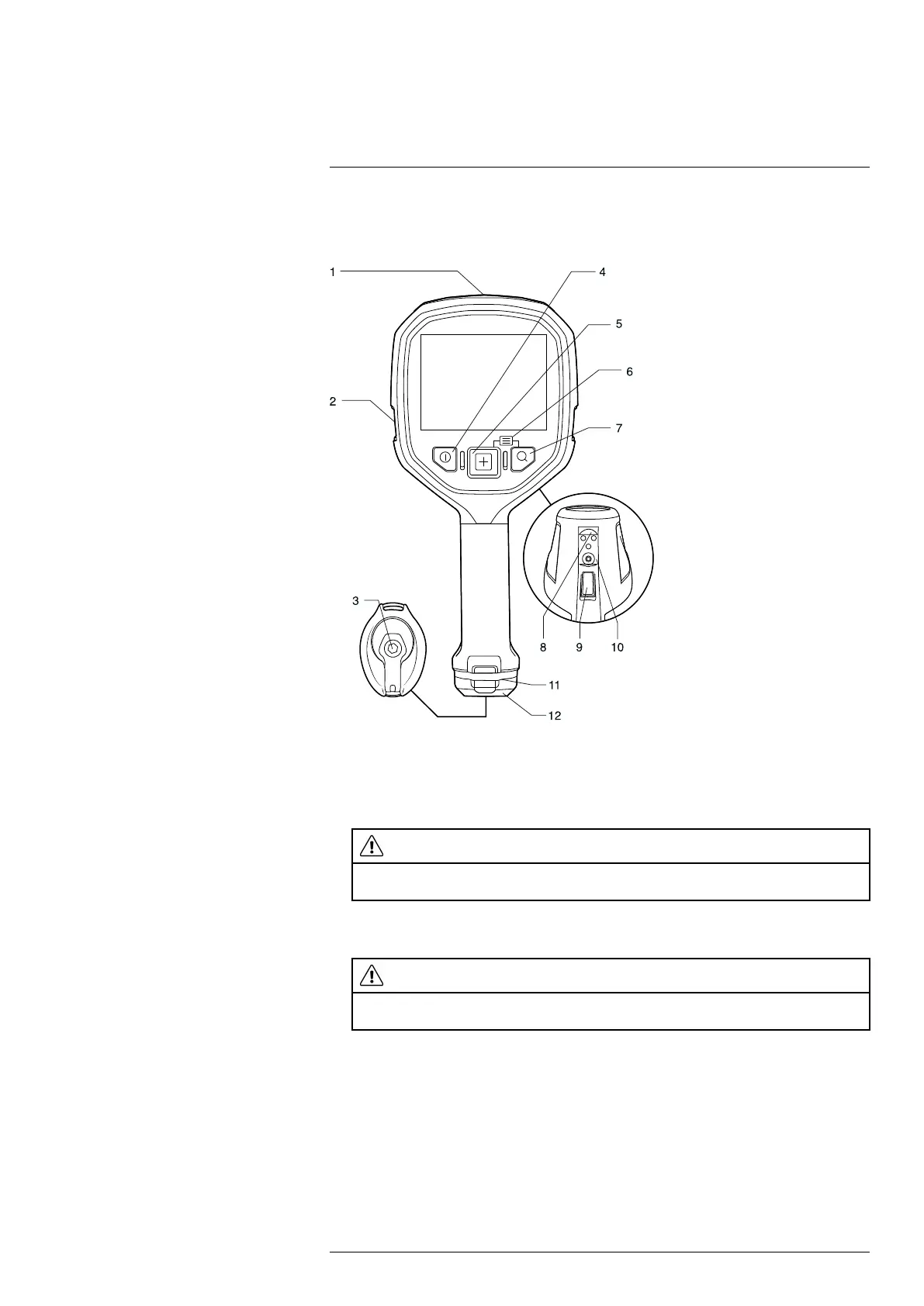
10.2 Camera (FLIR K65)
10.2.1 Figure
10.2.2 Explanation
1. USB Mini-B connector: Connect to a computer to download images using FLIR Tools.
The USB Mini-B connector is protected by a plastic cover that is fastened with a Torx
screw (T20).
CAUTION
Make sure that you do not use a torque value that is more than 80 Ncm on the Torx T20 screw.
Damage to the camera can occur if you do not obey this.
2. Attachment point for lanyard strap/neck strap (left and right sides).
3. Latch to secure the battery. The latch is fastened with a Torx screw (T20).
CAUTION
Make sure that you do not use a torque value that is more than 80 Ncm on the Torx T20 screw.
Damage to the camera can occur if you do not obey this.
4. On/off button. This button has three functions:
• Push the on/off button to turn on the camera.
• Push and hold the on/off button for more than 3 seconds but less than 10 seconds
to put the camera into standby mode. The camera then automatically turns off
after 6 hours.
• Push and hold the on/off button for more than 10 seconds to turn off the camera.
5. Mode button: Push repeatedly to select camera modes.
6. Access to the setup menus and stored images: Push the Mode + Zoom buttons.
7. Zoom button (zoom factor ×2).
8. Connectors for the in-truck charger.
#T559946; r. BA/41926/41970; en-US
20
 Loading...