OptiView
TM
Series II
Getting Started Guide
20
Analyzer Network Connections
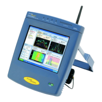
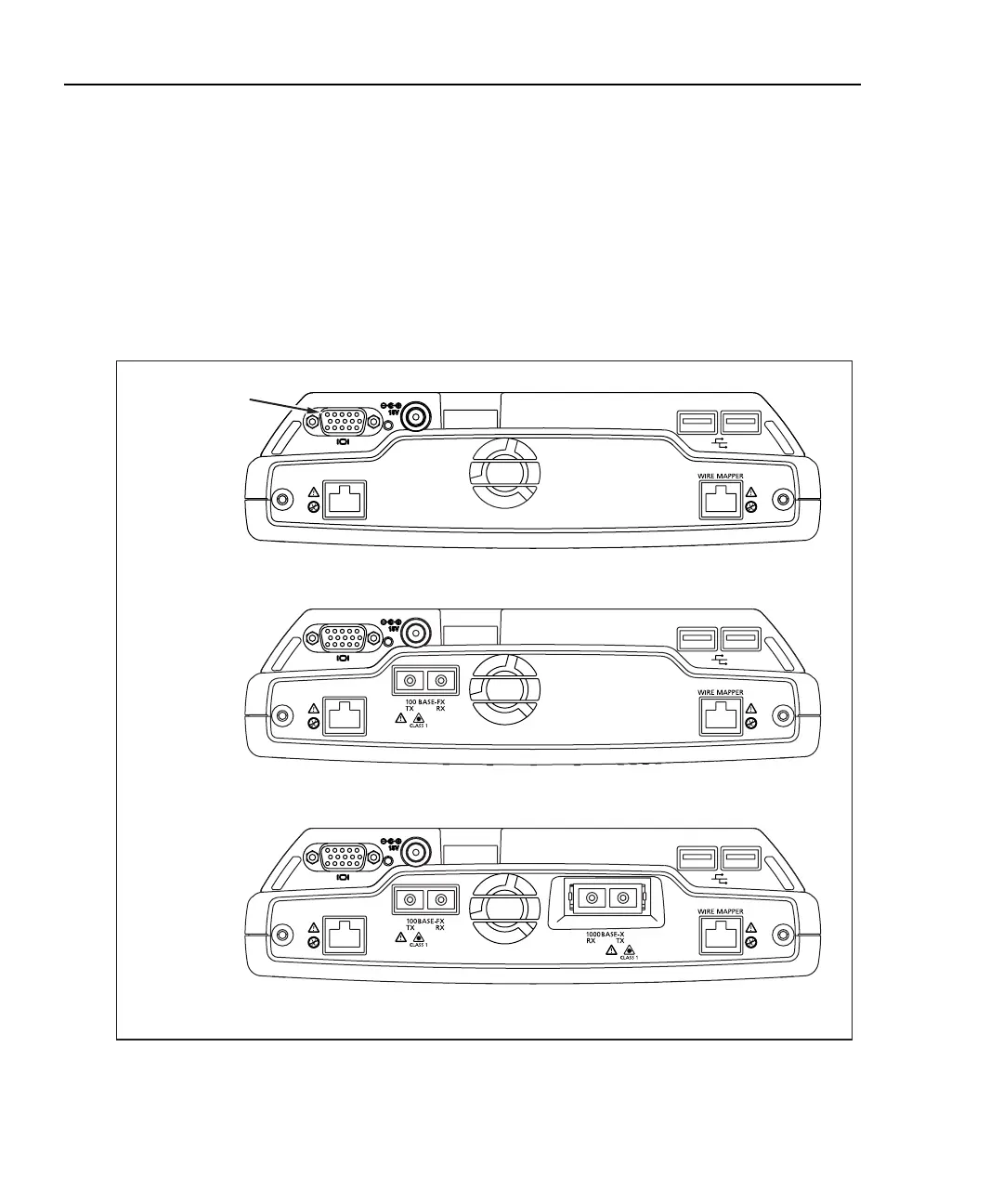
Figure 12 shows the top view of the OptiView
TM
Standard, Pro, and Pro Gigabit
Analyzers.
Note
The internal wire map adapter, labeled Wire Mapper, tests patch
cables. To test patch cables, connect a cable from the 10/100 BASE-
TX connector to the Wire Mapper connector. The test is
automatically run. Go to the Cable Test screen to view the results.
10BASE-T
100BASE-TX
10BASE-T
100BASE-TX
Pro Analyzer
Pro Gigabit Analyzer
10BASE-T
100BASE-TX
Standard Analyzer
VGA Out Port
aww10f.eps
Figure 12. Top View of the OptiViewTM Standard, Standard, Pro, and Pro Gigabit Analyzers
 Loading...