10
COOLING UNIT FK 2600 / 2601
Important! Please see your operating instructions FK 2600 / 2601
(article no.: 42,0410,0490) for information on MOUNTING and
START-UP.
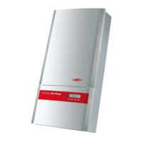
Fig.10b Design with central burner connection GWZ: Torch connection gas-
cooled
Design with central burner connection GWZ:
- Mount the gas adapter (44,0001,0785)
- Pull back the rubber sleeve from the rear of the torch
- Screw the hexagon nut (width across = 21) of the gas+current
connection onto the torch connector point on the machine
and tighten firmly
- Push the rubber sleeve back over the hexagon nut
- Plug the control plug into socket
and latch it
Important! Please see your torch’s instruction manual for techni-
cal details on the torch and for information on torch assembly, care
and maintenance.
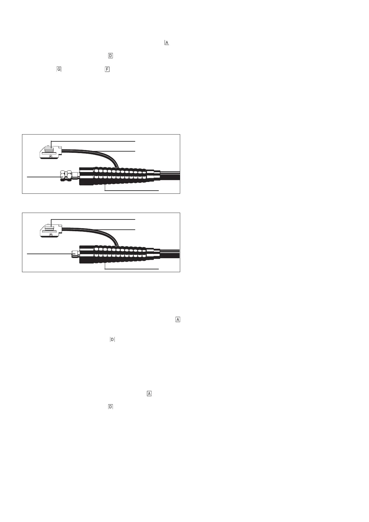
Design with Fronius central welding torch connection F:
- Insert welding torch bayonet connection in the central connec-
tion on the equipment side of the welding torch
and lock in
place by turning to the right
- Insert control plug in the socket and lock in place
Important! Please see your torch’s instruction manual for techni-
cal details on the torch and for information on torch assembly, care
and maintenance.
Fig.10c Design with Fronius central welding torch connection F: Torch connection
gas-cooled
Design with Fronius welding torch central connection F:
- Insert welding torch with bayonet connection into the central
connection on the equipment side of the welding torch
and
lock in place by turning to the right
- Insert control plug in the socket
and lock
- Connect water connections to the connection pieces on the
water feed and water return
Important! Please see your torch’s instruction manual for techni-
cal details on the torch and for information on torch assembly, care
and maintenance.
ASSEMBLING A GAS-COOLED TIG TORCH
Gas and current
connection
Control plug
Control lead
Hose sleeve
Gas and current
connection
Control plug
Control lead
Hose sleeve
 Loading...