 Loading...
Do you have a question about the Fujitsu PRIMERGY TX1320 M4 and is the answer not in the manual?
| Bus type | DMI3 |
|---|---|
| Tjunction | 100 °C |
| Scalability | 1S |
| Processor cache | 8 MB |
| Processor cores | 4 |
| Processor model | E-2124 |
| System bus rate | 8 GT/s |
| Processor socket | LGA 1151 (Socket H4) |
| Processor codename | Coffee Lake |
| Execute Disable Bit | Yes |
| Processor frequency | 3.3 GHz |
| Processor cache type | Smart Cache |
| Processor lithography | 14 nm |
| Processor manufacturer | Intel |
| Processor package size | 37.5 x 37.5 mm |
| Processor boost frequency | 4.3 GHz |
| Processor operating modes | 64-bit |
| Embedded options available | No |
| PCI Express configurations | 1x16, 2x8, 1x8+2x4 |
| Supported instruction sets | AVX 2.0, SSE4.1, SSE4.2 |
| Thermal Design Power (TDP) | 71 W |
| Number of processors installed | 1 |
| Maximum number of PCI Express lanes | 16 |
| Memory types supported by processor | DDR4-SDRAM |
| Memory clock speeds supported by processor | 2666 MHz |
| Memory bandwidth supported by processor (max) | 41.6 GB/s |
| Maximum internal memory supported by processor | 128 GB |
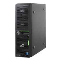
| Chassis type | Tower |
| Product color | Black |
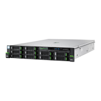
| HDD size | 2.5 \ |
| HDD interface | Serial ATA III, Serial Attached SCSI (SAS) |
| Optical drive type | DVD±RW |
| Total storage capacity | 0 GB |
| Maximum storage capacity | - TB |
| Number of HDDs installed | 0 |
| Compatible operating systems | Microsoft Hyper-V Server 2016 Microsoft Windows Server 2016 Datacenter Microsoft Windows Server 2016 Standard Microsoft Windows Server 2016 Essentials Microsoft Windows Storage Server 2016 Standard Microsoft Hyper-V Server 2012 R2 Microsoft Windows Server 2012 R2 Datacenter Microsoft Windows Server 2012 R2 Standard Microsoft Windows Server 2012 R2 Essentials Microsoft Windows Server 2012 R2 Foundation Microsoft Windows Storage Server 2012 R2 Standard Microsoft Hyper-V Server 2012 Microsoft Windows Server 2012 Datacenter Microsoft Windows Server 2012 Standard Microsoft Windows Server 2012 Essentials Microsoft Windows Server 2012 Foundation VMware vSphere 6.5 VMware vSphere 6.0 SUSE Linux Enterprise Server 12 Red Hat Enterprise Linux 7 Univention Corporate Server 4 |
| Internal memory | 16 GB |
| Maximum internal memory | 64 GB |
| LAN controller | Intel i210 |
| Cabling technology | 10/100/1000Base-T(X) |
| Ethernet interface type | Gigabit Ethernet |
| USB 2.0 ports quantity | USB 2.0 ports have a data transmission speed of 480 Mbps, and are backwards compatible with USB 1.1 ports. You can connect all kinds of peripheral devices to them. |
| Ethernet LAN (RJ-45) ports | 3 |
| Power supply | 450 W |
| Operating temperature (T-T) | 5 - 45 °C |
| Operating relative humidity (H-H) | 10 - 85 % |
| PCI Express slots version | 3.0 |
| PCI Express x4 (Gen 3.x) slots | 2 |
| On-board graphics card model | Not available |
| Processor ARK ID | 134856 |
| Intel Secure Key Technology version | 1.00 |
| Depth | 399 mm |
|---|---|
| Width | 98 mm |
| Height | 340 mm |