Garmin G5 Electronic Flight Instrument Part 23 AML STC Maintenance Manual 190-01112-11
Rev. 7
Page 17 of 54
5.1.7 GPS Navigation Information (Installations with a GAD 29/29B Installed)
5.1.7.1 GPS VFR Displayed on G5
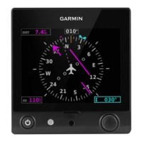
If the GPS navigation information is removed from the G5 HSI display and GPS VFR is displayed:
1)
On the G5 in configuration mode, select the Device Information page, select A429 and verify
there is a Green Check by A429. If there is a Red-X by A429 proceed to the next step.
2)
Check the ARINC 429 wiring connected between the G5 and the GAD 29/29B using the
instructions in the General section above.
3)
The GAD 29/29B has an LED on the outer case that indicates the LRUs current status. The status
indications are:
Table 5-2, GAD 29/29B Status LED Indications
4)
If the LED indication is ‘No Light’ verify the circuit breaker, power and ground wiring between
the GAD 29/29B circuit breaker and GAD 29/29B. If proper power is available to the GAD
29/29B replace the GAD 29/29B with a known good unit.
5)
If the LED indication is Steady Green Inspect and verify the CAN Bus wiring between the G5 and
GAD 29/29B
a.
With power removed, remove a connector from one of the devices that is not located at
either of the extreme ends of the CAN bus.
b.
Using an ohm meter, verify that the resistance between the CAN HI and CAN LO pins on
the connector is 60 ohms. This will verify that the CAN backbone is properly terminated at
each end (two 120 ohm terminating resistors in parallel).
c.
A resistance of 120 ohms indicates that one of the two required CAN terminations is
missing.
d.
A resistance of 40 ohms or less indicates that too many terminations are installed.
e.
Verify that the CAN HI and CAN LO signals are not swapped, shorted together, or open-
circuited at any LRU connector.
f.
Verify that the CAN HI and CAN LO signals are not shorted to ground (this can happen
when shielded wire is installed incorrectly).
NOTE
If a Lightning Protection Module is installed, check for continuity between backshell leads per
Garmin G5 Electronic Flight Instrument Part 23 AML STC Installation Manual, 190-01112-10
section 5.
6)
If the LED indication is ‘Red’, replace the GAD 29/29B with a known good unit.

 Loading...


