2 INSTALLATION
g
GE Power Management
10
2.3 External Connections
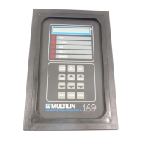
The connections made to the 169 relay will vary depending on the programming of the unit. It is not necessary to
use all of the connections provided; a minimal configuration would include supply power, three phase current CT
inputs and the Trip relay contacts wired in series with the contactor control relay or circuit breaker shunt trip coil.
Connections to these and the other terminals outlined below will be explained in the following sections. Figures 2-4,
2-6, 2-7 show typical connections to the 169 relay.
NOTE: The rear of the 169 relay shows output relay contacts in their power down state. Figures 2-4, 2-6, 2-7 show
output relay contacts with power applied, no trips or alarms, Factory Configurations, i.e. TRIP - fail-safe, ALARM -
non-fail-safe, AUX.1 - non-fail-safe, AUX.2 - fail-safe). See Figure 2-5 for a complete list of all possible output relay
contact states. See page 62 for a description of the RELAY FAILSAFE CODE.
Table 2-1 169 External Connections
Inputs
•
Supply Power L, G, N
•
Phase CTs
•
Ground Fault CTs
•
6 Stator RTDs
•
2 additional RTDs on the 169, 4 on the 169 Plus
•
Emergency Restart keyswitch
•
External Reset pushbutton
•
Programming Access jumper or keyswitch
•
Speed Switch input on the 169 Plus
•
Differential Relay input on the 169 Plus
•
Spare Input on the 169 Plus
Outputs
•
2 Sets of Relay Contacts (NO/NC) on the 169, 4 on the 169 Plus
•
Programmable Analog Current Output Terminals
•
RS 422 Serial Communication Port on the 169 Plus
 Loading...