TABLE OF CONTENTS
g
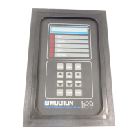
GE Power Management
i
1.1 Motor Protection Requirements
........................................................................................................... 1
1.2 169 Relay Features
................................................................................................................................. 1
1.3 Typical Applications
............................................................................................................................... 3
1.4 Technical Specifications
....................................................................................................................... 4
2.1 Physical Dimensions
............................................................................................................................. 7
2.2 Mounting
................................................................................................................................................. 9
2.3 External Connections
.......................................................................................................................... 10
2.4 Control Power
....................................................................................................................................... 15
2.5 Phase C.T.s
............................................................................................................................................ 15
2.6 Ground Fault C.T.
................................................................................................................................. 16
2.7 Trip Relay Contacts
.............................................................................................................................. 16
2.8 Alarm Relay Contacts
.......................................................................................................................... 16
2.9 Auxiliary Relay #1 Contacts (169 Plus)
.............................................................................................. 17
2.10 Auxiliary Relay #2 Contacts (169 Plus)
............................................................................................ 17
2.11 RTD Sensor Connections
.................................................................................................................. 17
2.12 Emergency Restart Terminals
.......................................................................................................... 18
2.13 External Reset Terminals
.................................................................................................................. 18
2.14 Analog Output Terminals
................................................................................................................... 18
2.15 Differential Relay Terminals (169 Plus)
............................................................................................ 19
2.16 Speed Switch Terminals (169 Plus)
.................................................................................................. 19
2.17 Programming Access Terminals
...................................................................................................... 19
2.18 RS-422 Serial Communications Terminals (169 Plus)
................................................................... 19
2.19 Display Adjustment
............................................................................................................................ 20
2.20 Front Panel Faceplate
........................................................................................................................ 20
2.21 Spare Input Terminals (169 Plus)
..................................................................................................... 20
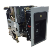
2.22 169 Drawout Relay
............................................................................................................................. 21
3.1 Controls and Indicators
....................................................................................................................... 26
3.2 169 Relay Display Modes
.................................................................................................................... 30
3.3 ACTUAL VALUES Mode........................................................................................................................ 30
3.4 SETPOINTS Mode
................................................................................................................................41
3.5 HELP Mode
.......................................................................................................................................... 58
3.6 TRIP/ALARM Mode
............................................................................................................................... 58
3.7 Phase C.T. and Motor Full Load Current Setpoints
.......................................................................... 61
3.8 Acceleration Time Setpoint
................................................................................................................. 61
3.9 Number of Starts/Hour Setpoint
......................................................................................................... 61
 Loading...