1 INTRODUCTION
g
GE Power Management
2
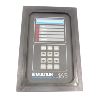
The 169 Plus relay provides a complete statistical record of the motor being protected. The total motor running
hours, the number of motor starts, and the total number of relay trips since the last commissioning are stored and
can be viewed on the display. As well, the number of short circuit, RTD, ground fault, unbalance, overload, start, and
rapid trips can be recalled by simple keypad commands. These values are stored along with all of the relay
setpoints in a non-volatile memory within the relay. Thus, even when control power is removed from the 169 Plus,
the statistical record and all relay setpoints will remain intact.
The 169 can provide one of various output signals for remote metering or programmable controller attachment.
Analog signals of motor current as a percentage of full load, hottest stator RTD temperature, percentage of phase
CT secondary current, or motor thermal capacity are available by simple field programming. A total of four output
relays are provided on the 169 Plus, including a latched trip relay, an alarm relay, and two auxiliary relays. The
model 169 provides a latched trip relay and an alarm relay. All output relays may be programmed via the keypad to
trip on specific types of faults or overloads.
When an output relay becomes active, the 169 will display the cause of the trip, and if applicable, the lock-out time
remaining. Pre-trip values of motor current, unbalance, ground fault current, and maximum stator RTD temperature
are stored by the 169 and may be recalled using the keypad.
The correct operation of the Multilin 169 relay is continually checked by a built-in firmware self-test routine. If any
part of the relay malfunctions under this self-test, an alarm indication will tell the operator that service is required.
Table 1-1 Model 169 and 169 Plus Relay Features
Protection Features
•
Overloads
•
Stator Winding Overtemperature (Alarm and Trip)
•
Multiple Starts
•
Short Circuit
•
Locked Rotor
•
Rapid Trip/Mechanical Jam
•
Unbalance/Single Phasing
•
Ground Fault (Alarm and Trip)
•
Phase Reversal
•
Bearing Overtemperature (Alarm and Trip)
•
Undercurrent
•
Variable Lock-Out Time
Operational Features
•
Microcomputer controlled
•
Keypad programmable
•
48 character alphanumeric display
•
Built-in "HELP" function
•
Eight selectable standard overload curves
•
User defined custom overload curve capability (169 Plus)
•
Continual relay circuitry self-check
Monitoring and Display Features
•
Negative sequence phase current unbalance measurement
•
Ground fault (earth leakage) current measurement
•
Up to six stator RTD inputs
•
Two additional RTD inputs on the model 169, four on the 169 Plus
•
Monitoring of motor ambient air temperature
•
Display of all SETPOINTS or ACTUAL VALUES upon request
•
Display of relay TRIP/ALARM and HELP messages
 Loading...