2 INSTALLATION
g
GE Power Management
20
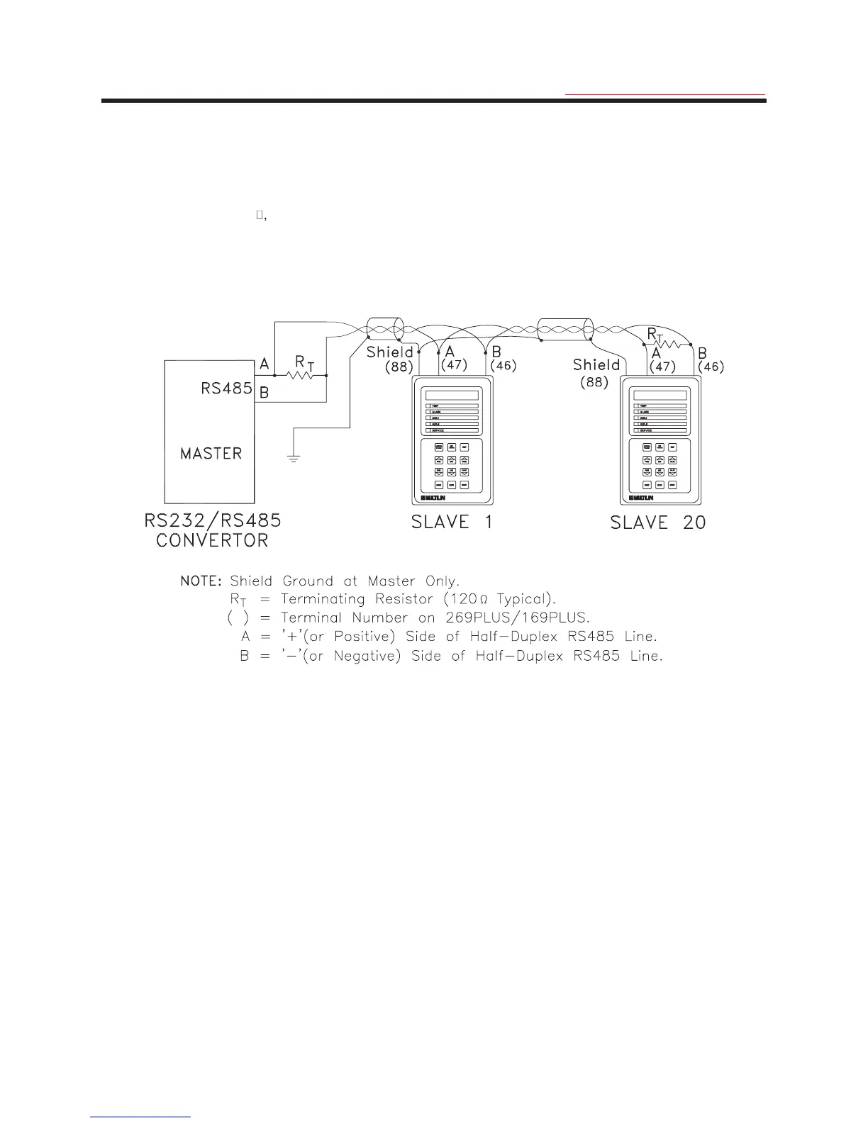
The wires joining relays in the communication link should be a twisted pair. These wires should be routed away from
high power AC lines and other sources of electrical noise. The total length of the communications link should not
exceed 4000 feet. When connecting units in a communication link each 169 Plus relay must have terminal 47
connected to terminal 47 of the next unit in the link, and terminal 46 connected to terminal 46.
As shown in Figure 2-9 the first and last devices in the link should have a terminating resistor placed across
terminals 46 and 47. The value of these resistors should match the characteristic impedance of the line wire being
used. A typical value is 50
, 1/4 watt.
Connection to the 169 is made via a terminal block which can accommodate up to #12 AWG multi-strand wire.
Note: The difference in potentials between serial master ground and the 169 Plus slave (terminal 42) must
not exceed 10 volts. If a large difference in ground potentials does exist, communication on the serial
communication link will not be possible. In addition damage to the 169 Plus may result.
Figure 2-9 Serial Communication Link Wiring
2.19 Display Adjustment
Once the 169 relay has been installed and input power applied, the contrast of the LCD display may have to be
adjusted. This adjustment has been made at the factory for average lighting conditions and a standard viewing
angle but can be changed to optimize the display readability in different environments. To alter the display contrast
the trimpot on the rear of the unit marked "CONTRAST" must be adjusted with a small slotted screwdriver.
2.20 Front Panel Faceplate
The front panel faceplate is composed of a polycarbonate material that can be cleaned with isopropyl or denatured
alcohol, freon, naphtha, or mild soap and water.
2.21 Spare Input Terminals (169 Plus)
Terminals 44 and 45 are provided for an additional relay contact input. A contact closure between these terminals
will cause a "SPARE INPUT TRIP" and/or a "SPARE INPUT ALARM" after the appropriate time delay (page 5 of
SETPOINTS). These terminals must be open circuited in order to reset the relay after a SPARE INPUT TRIP or
ALARM.
A twisted pair of wires should be used. Connection to the 169 is made via a terminal block which can accommodate
up to #12 AWG multi-strand wire.
 Loading...